How to Use Connector 3 In 6 Out: Examples, Pinouts, and Specs
Introduction
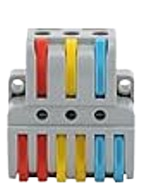
The Connector 3 In 6 Out is a versatile electronic component designed to distribute three input signals to six output channels. This component is particularly useful in circuits where multiple devices or modules need to receive the same signals simultaneously. It simplifies signal routing and reduces the need for complex wiring, making it an essential tool in prototyping, testing, and production environments.
Explore Projects Built with Connector 3 In 6 Out


Explore Projects Built with Connector 3 In 6 Out
Common Applications and Use Cases
- Signal distribution in audio, video, or data systems
- Prototyping circuits with multiple modules requiring the same input
- Parallel signal routing in microcontroller-based projects
- Splitting control signals for multiple actuators or sensors
- Simplifying wiring in complex electronic systems
Technical Specifications
The Connector 3 In 6 Out is a passive component that does not amplify or modify the signals passing through it. Below are its key technical details:
General Specifications
- Input Channels: 3
- Output Channels: 6 (2 outputs per input channel)
- Maximum Voltage Rating: 30V DC
- Maximum Current Rating: 2A per channel
- Connector Type: Screw terminal or pin header (varies by model)
- Material: High-quality plastic housing with copper alloy contacts
- Operating Temperature Range: -20°C to 70°C
Pin Configuration and Descriptions
The Connector 3 In 6 Out typically has the following pin layout:
| Pin | Description |
|---|---|
| IN1 | Input signal 1 |
| IN2 | Input signal 2 |
| IN3 | Input signal 3 |
| OUT1A | Output 1A (connected to IN1) |
| OUT1B | Output 1B (connected to IN1) |
| OUT2A | Output 2A (connected to IN2) |
| OUT2B | Output 2B (connected to IN2) |
| OUT3A | Output 3A (connected to IN3) |
| OUT3B | Output 3B (connected to IN3) |
Usage Instructions
How to Use the Connector in a Circuit
Connect Input Signals:
- Attach the input signals to the IN1, IN2, and IN3 terminals using screw terminals or pin headers.
- Ensure the input signals do not exceed the maximum voltage and current ratings.
Connect Output Devices:
- Connect the devices or modules that need the signals to the corresponding output terminals (e.g., OUT1A and OUT1B for IN1).
- Each input signal is distributed to two outputs, so ensure the connected devices are compatible with the shared signal.
Verify Connections:
- Double-check all connections to ensure there are no loose wires or short circuits.
- Use a multimeter to confirm continuity if necessary.
Power On:
- Power on the circuit and verify that the signals are correctly distributed to the output channels.
Important Considerations and Best Practices
- Signal Integrity: Since the connector is a passive component, it does not amplify signals. Ensure the input signals are strong enough to drive all connected outputs.
- Current Sharing: Avoid exceeding the maximum current rating of 2A per channel. If multiple devices are connected to the same output, ensure their combined current draw is within the limit.
- Avoid Overvoltage: Do not apply voltages higher than 30V DC to the inputs, as this may damage the connector or connected devices.
- Secure Connections: Use appropriate tools to tighten screw terminals or ensure pin headers are firmly seated to prevent accidental disconnections.
Example: Using with an Arduino UNO
The Connector 3 In 6 Out can be used to distribute signals from an Arduino UNO to multiple devices. For example, you can use it to send PWM signals to control multiple LEDs or motors.
Sample Code
// Example: Distributing PWM signals from Arduino UNO to multiple outputs
// This code generates PWM signals on pins 3, 5, and 6 to control LEDs or motors.

// Define the PWM output pins
const int pwmPin1 = 3; // Signal for IN1
const int pwmPin2 = 5; // Signal for IN2
const int pwmPin3 = 6; // Signal for IN3

void setup() {
  // Set the PWM pins as outputs
  pinMode(pwmPin1, OUTPUT);
  pinMode(pwmPin2, OUTPUT);
  pinMode(pwmPin3, OUTPUT);
}

void loop() {
  // Generate a PWM signal on each pin
  analogWrite(pwmPin1, 128); // 50% duty cycle on IN1
  analogWrite(pwmPin2, 64);  // 25% duty cycle on IN2
  analogWrite(pwmPin3, 192); // 75% duty cycle on IN3

  // Add a delay to observe the output
  delay(1000);
}
Troubleshooting and FAQs
Common Issues and Solutions
No Signal at Outputs:
- Cause: Loose or incorrect connections.
- Solution: Verify that all input and output connections are secure and correctly matched.
Signal Degradation:
- Cause: Input signal strength is insufficient to drive multiple outputs.
- Solution: Use a signal amplifier or buffer circuit to strengthen the input signal.
Overheating:
- Cause: Exceeding the maximum current rating.
- Solution: Ensure the total current draw of connected devices does not exceed 2A per channel.
Short Circuit:
- Cause: Wires touching or incorrect wiring.
- Solution: Inspect the wiring and ensure there are no exposed wires or shorts.
FAQs
Q: Can I use this connector for AC signals?
A: No, the Connector 3 In 6 Out is designed for DC signals only. Using it with AC signals may result in signal loss or damage.Q: Can I connect more than two devices to a single output?
A: While technically possible, it is not recommended as it may degrade signal quality and exceed the current rating.Q: Is this connector suitable for high-frequency signals?
A: The connector is best suited for low- to mid-frequency signals. For high-frequency applications, consider using a specialized signal splitter.Q: Can I use this connector with breadboards?
A: Yes, if the model has pin headers, it can be easily used with breadboards. For screw terminal models, additional wiring may be required.
This documentation provides all the necessary details to effectively use the Connector 3 In 6 Out in your projects.