Cirkit Designer Logo
Cirkit Designer
Your all-in-one circuit design IDE
Home / 
Component Documentation

How to Use Adafruit MCP4728: Examples, Pinouts, and Specs

Image of Adafruit MCP4728
Cirkit Designer LogoDesign with Adafruit MCP4728 in Cirkit Designer

Introduction

The Adafruit MCP4728 is a versatile and precise multi-channel digital-to-analog converter (DAC) module. It is equipped with four independent 12-bit DAC channels, enabling the conversion of digital signals into analog voltages. This module is ideal for applications requiring multiple analog outputs, such as generating audio signals, controlling variable lighting, or driving analog sensors. It interfaces with microcontrollers via the I2C protocol, making it a convenient addition to projects that require analog capabilities but are limited to digital-only outputs.

Explore Projects Built with Adafruit MCP4728

Use Cirkit Designer to design, explore, and prototype these projects online. Some projects support real-time simulation. Click "Open Project" to start designing instantly!
ESP32-Based Smart Weather Station with LED Display and Multiple Sensors
Image of Copy of Zegarek (1): A project utilizing Adafruit MCP4728 in a practical application
This circuit is a sensor and display system powered by an ESP32 microcontroller. It integrates multiple sensors (BH1750 light sensor, BMP280 pressure sensor, DS3231 RTC, and DS18B20 temperature sensor) and drives a series of MAX7219 8x8 LED matrices for visual output. The ESP32 communicates with the sensors via I2C and controls the LED matrices to display data.
Cirkit Designer LogoOpen Project in Cirkit Designer
Arduino-Based RGB Color Detection System with OLED and LCD Displays
Image of 1: A project utilizing Adafruit MCP4728 in a practical application
This circuit uses an Arduino UNO to interface with an Adafruit TCS34725 RGB color sensor, a 128x64 OLED display, and a 16x2 I2C LCD. The Arduino reads color data from the sensor and displays the color information on both the OLED and LCD screens.
Cirkit Designer LogoOpen Project in Cirkit Designer
Raspberry Pi 5 and Adafruit MCP4728 Based Digital-to-Analog Converter
Image of JUST: A project utilizing Adafruit MCP4728 in a practical application
This circuit connects a Raspberry Pi 5 to an Adafruit MCP4728 DAC via I2C communication. The Raspberry Pi provides power and ground to the DAC, and uses GPIO pins 2 and 3 for SDA and SCL lines respectively to control the DAC.
Cirkit Designer LogoOpen Project in Cirkit Designer
Battery-Powered Smart Light with Proximity Sensor and OLED Display using Adafruit QT Py RP2040
Image of lab: A project utilizing Adafruit MCP4728 in a practical application
This circuit is a portable, battery-powered system featuring an Adafruit QT Py RP2040 microcontroller that interfaces with an OLED display, a proximity sensor, an accelerometer, and an RGB LED strip. The system is powered by a lithium-ion battery with a step-up boost converter to provide 5V for the LED strip, and it includes a toggle switch for power control. The microcontroller communicates with the sensors and display via I2C.
Cirkit Designer LogoOpen Project in Cirkit Designer

Explore Projects Built with Adafruit MCP4728

Use Cirkit Designer to design, explore, and prototype these projects online. Some projects support real-time simulation. Click "Open Project" to start designing instantly!
Image of Copy of Zegarek (1): A project utilizing Adafruit MCP4728 in a practical application
ESP32-Based Smart Weather Station with LED Display and Multiple Sensors
This circuit is a sensor and display system powered by an ESP32 microcontroller. It integrates multiple sensors (BH1750 light sensor, BMP280 pressure sensor, DS3231 RTC, and DS18B20 temperature sensor) and drives a series of MAX7219 8x8 LED matrices for visual output. The ESP32 communicates with the sensors via I2C and controls the LED matrices to display data.
Cirkit Designer LogoOpen Project in Cirkit Designer
Image of 1: A project utilizing Adafruit MCP4728 in a practical application
Arduino-Based RGB Color Detection System with OLED and LCD Displays
This circuit uses an Arduino UNO to interface with an Adafruit TCS34725 RGB color sensor, a 128x64 OLED display, and a 16x2 I2C LCD. The Arduino reads color data from the sensor and displays the color information on both the OLED and LCD screens.
Cirkit Designer LogoOpen Project in Cirkit Designer
Image of JUST: A project utilizing Adafruit MCP4728 in a practical application
Raspberry Pi 5 and Adafruit MCP4728 Based Digital-to-Analog Converter
This circuit connects a Raspberry Pi 5 to an Adafruit MCP4728 DAC via I2C communication. The Raspberry Pi provides power and ground to the DAC, and uses GPIO pins 2 and 3 for SDA and SCL lines respectively to control the DAC.
Cirkit Designer LogoOpen Project in Cirkit Designer
Image of lab: A project utilizing Adafruit MCP4728 in a practical application
Battery-Powered Smart Light with Proximity Sensor and OLED Display using Adafruit QT Py RP2040
This circuit is a portable, battery-powered system featuring an Adafruit QT Py RP2040 microcontroller that interfaces with an OLED display, a proximity sensor, an accelerometer, and an RGB LED strip. The system is powered by a lithium-ion battery with a step-up boost converter to provide 5V for the LED strip, and it includes a toggle switch for power control. The microcontroller communicates with the sensors and display via I2C.
Cirkit Designer LogoOpen Project in Cirkit Designer

Common Applications and Use Cases

  • Audio signal generation
  • LED dimming and color control
  • Precision control for actuators
  • Analog sensor emulation
  • Function generators

Technical Specifications

Key Technical Details

  • Resolution: 12-bit per channel
  • Number of Channels: 4
  • Communication Interface: I2C
  • Supply Voltage: 2.7V to 5.5V
  • Output Voltage Range: 0V to VDD
  • Internal Voltage Reference: Selectable between VDD and internal reference
  • I2C Addresses: 8 selectable addresses via jumpers

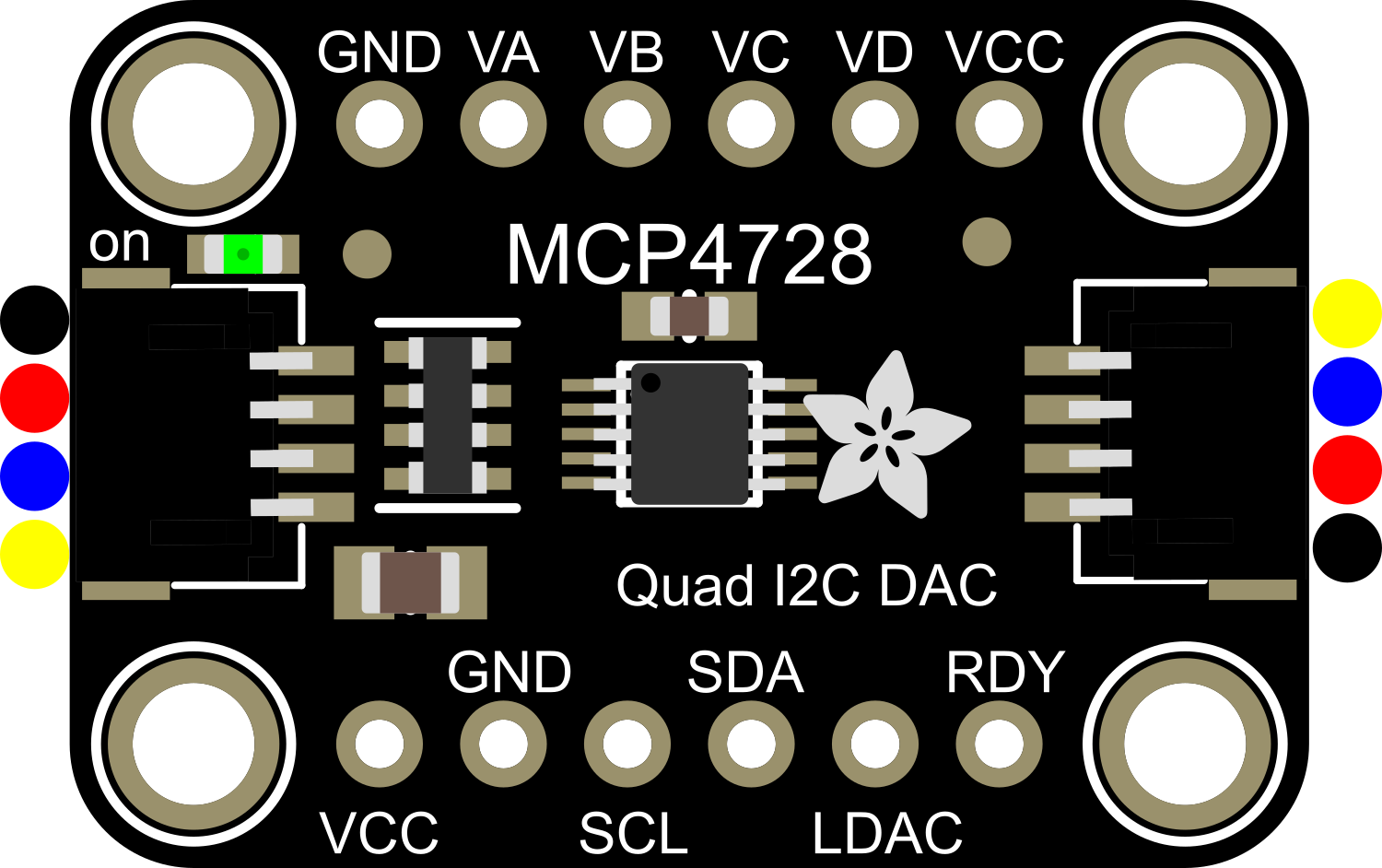
Pin Configuration and Descriptions

Pin Number Pin Name Description
1 VDD Power supply (2.7V to 5.5V)
2 GND Ground
3 SCL I2C clock line
4 SDA I2C data line
5 A0 Address select bit 0 (I2C address pin)
6 A1 Address select bit 1 (I2C address pin)
7 A2 Address select bit 2 (I2C address pin)
8 VOUTA Analog output for DAC channel A
9 VOUTB Analog output for DAC channel B
10 VOUTC Analog output for DAC channel C
11 VOUTD Analog output for DAC channel D

Usage Instructions

How to Use the Component in a Circuit

  1. Connect the VDD pin to a power supply within the range of 2.7V to 5.5V.
  2. Connect the GND pin to the ground of your power supply.
  3. Connect the SCL and SDA pins to the I2C clock and data lines on your microcontroller.
  4. Set the A0, A1, and A2 pins according to the desired I2C address.
  5. Connect the VOUT pins (A, B, C, D) to your analog input devices.

Important Considerations and Best Practices

  • Ensure that the power supply voltage does not exceed the specified range.
  • Use pull-up resistors on the SCL and SDA lines if they are not provided by the microcontroller.
  • Avoid running high-speed I2C communication as it may affect the DAC performance.
  • When using multiple MCP4728 modules, ensure that each has a unique I2C address.
  • To minimize noise, keep analog and digital circuits separate and use proper decoupling techniques.

Example Code for Arduino UNO

#include <Wire.h>
#include <Adafruit_MCP4728.h>

Adafruit_MCP4728 mcp;

void setup() {
  Wire.begin(); // Start I2C bus
  mcp.begin(0x60); // Initialize MCP4728, default address 0x60

  // Set the voltage output of all channels to mid-scale
  mcp.setChannelValue(MCP4728_CHANNEL_A, 2048);
  mcp.setChannelValue(MCP4728_CHANNEL_B, 2048);
  mcp.setChannelValue(MCP4728_CHANNEL_C, 2048);
  mcp.setChannelValue(MCP4728_CHANNEL_D, 2048);
  mcp.saveToEEPROM(); // Save the current settings to EEPROM
}

void loop() {
  // Example: Cycle through voltage levels on channel A
  for (uint16_t i = 0; i < 4096; i++) {
    mcp.setChannelValue(MCP4728_CHANNEL_A, i);
    delay(10);
  }
}

Troubleshooting and FAQs

Common Issues

  • No Output Voltage: Ensure that the I2C communication is established correctly and the MCP4728 is powered.
  • Incorrect Voltage Output: Verify that the input digital value is within the correct range (0-4095) and that the reference voltage is set correctly.
  • I2C Communication Errors: Check pull-up resistors on SCL and SDA lines and ensure that there are no address conflicts with other I2C devices.

Solutions and Tips for Troubleshooting

  • Use the Wire.endTransmission() function to check for I2C errors. A return value of 0 indicates success.
  • If using long wires for I2C communication, consider lowering the clock speed to improve signal integrity.
  • Ensure that the power supply is stable and within the specified voltage range.

FAQs

Q: Can I use the MCP4728 with a 3.3V system? A: Yes, the MCP4728 can operate at voltages as low as 2.7V.

Q: How do I change the I2C address of the MCP4728? A: The I2C address can be changed by adjusting the A0, A1, and A2 pins.

Q: Can I save the DAC output values so they persist after power cycling? A: Yes, the saveToEEPROM() function will store the current DAC values to the internal EEPROM.

Q: Is it possible to update all DAC channels simultaneously? A: Yes, the MCP4728 supports a multi-write command to update all channels at once.