
How to Use Adafruit 8x16 LED Matrix FeatherWing - Red: Examples, Pinouts, and Specs
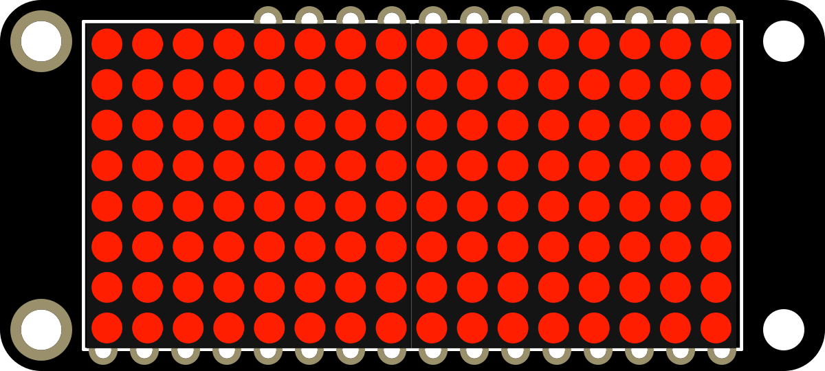
 Design with Adafruit 8x16 LED Matrix FeatherWing - Red in Cirkit Designer
Introduction
The Adafruit 8x16 LED Matrix FeatherWing - Red (Manufacturer Part ID: 3152) is a compact and versatile LED matrix display module designed specifically for use with Adafruit Feather boards. It features 128 red LEDs arranged in an 8x16 grid, making it ideal for creating visual displays, animations, scrolling text, and other dynamic visual effects. This module is powered by the HT16K33 LED driver chip, which simplifies control and reduces the number of required pins.
Explore Projects Built with Adafruit 8x16 LED Matrix FeatherWing - Red
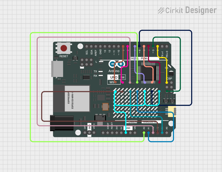 Open Project in Cirkit Designer
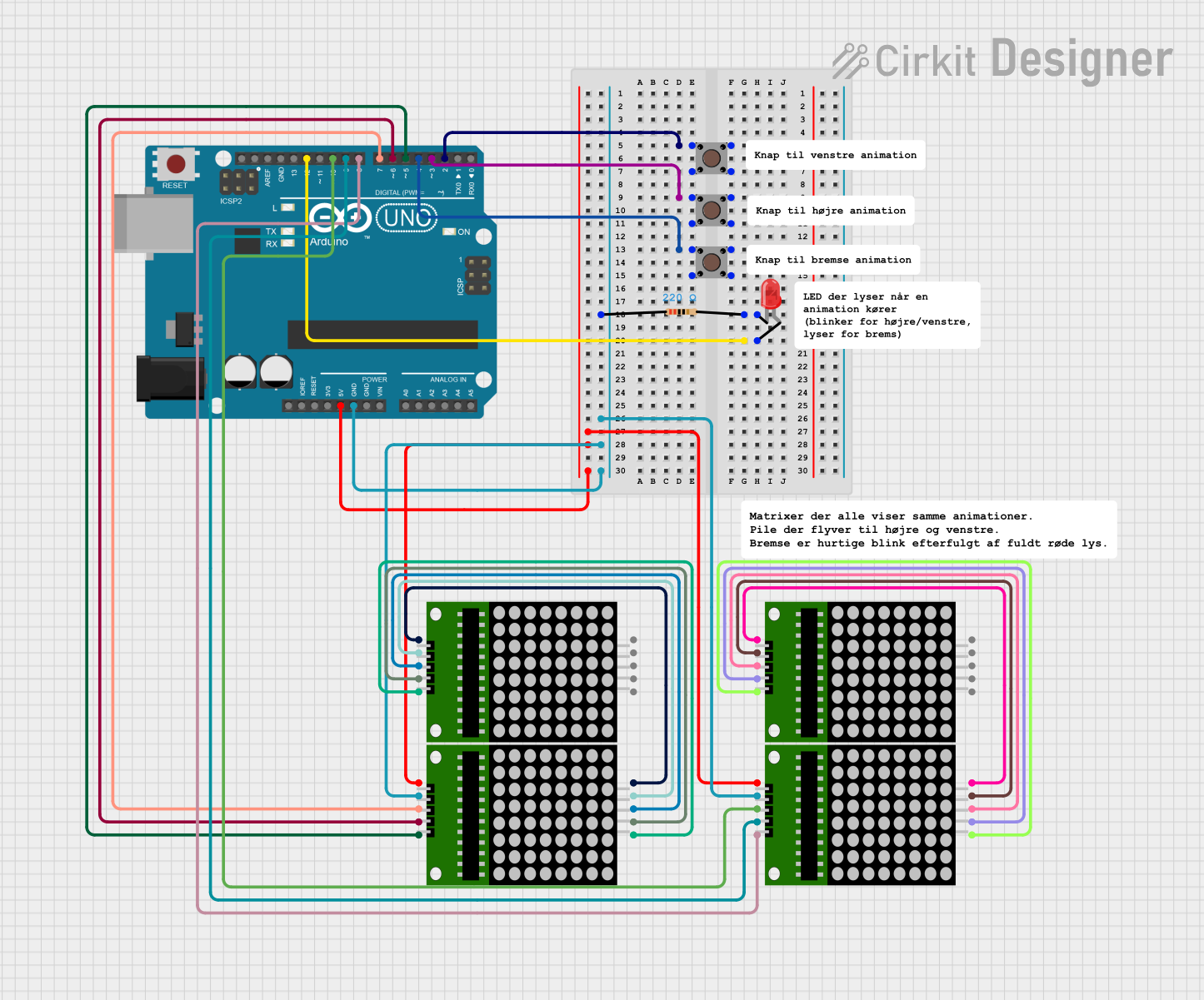 Open Project in Cirkit Designer
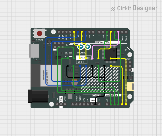 Open Project in Cirkit Designer
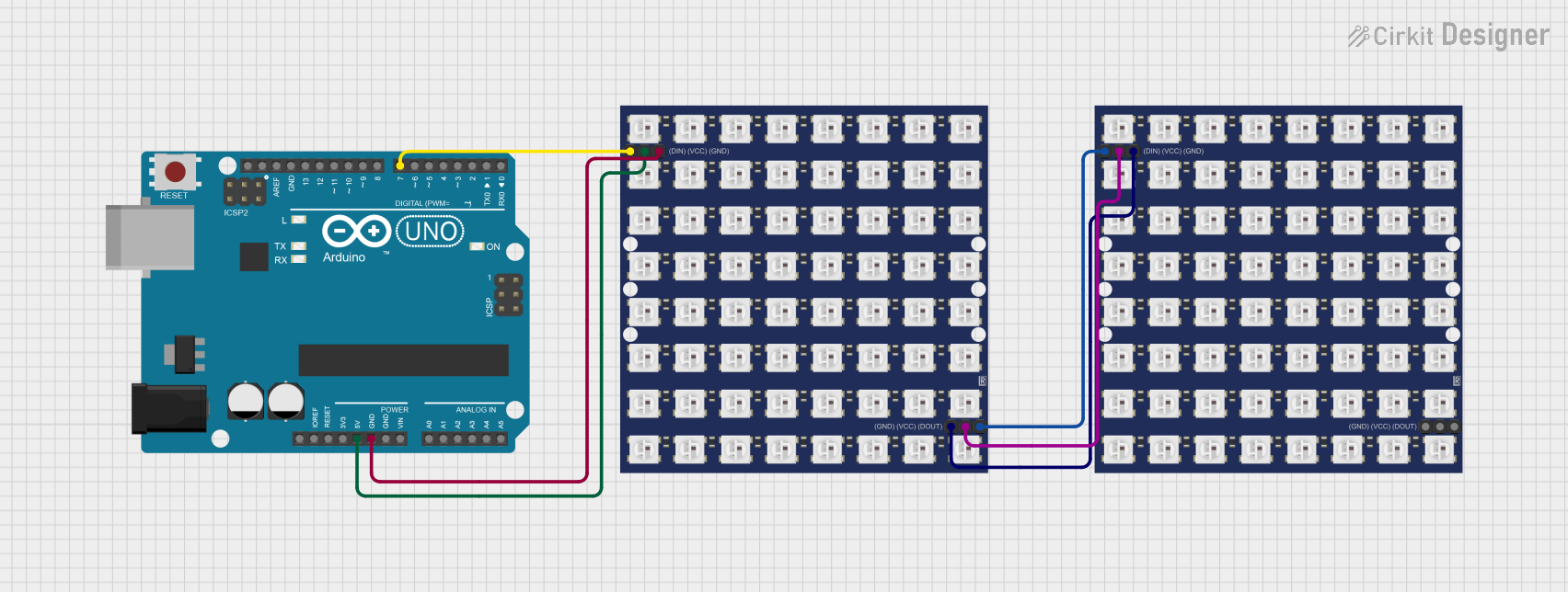 Open Project in Cirkit Designer
Explore Projects Built with Adafruit 8x16 LED Matrix FeatherWing - Red
Open Project in Cirkit DesignerOpen Project in Cirkit DesignerOpen Project in Cirkit DesignerOpen Project in Cirkit DesignerCommon Applications and Use Cases
- Scrolling text displays
- Visual indicators for IoT projects
- Animations and graphics
- Compact signage
- Educational and prototyping projects
Technical Specifications
Below are the key technical details and pin configuration for the Adafruit 8x16 LED Matrix FeatherWing - Red:
Key Technical Details
| Parameter | Specification |
|---|---|
| Manufacturer | Adafruit |
| Manufacturer Part ID | 3152 |
| LED Configuration | 8x16 grid (128 red LEDs) |
| Driver Chip | HT16K33 |
| Operating Voltage | 3.3V (compatible with Feather boards) |
| Communication Protocol | I2C |
| Default I2C Address | 0x70 (configurable) |
| Dimensions | 50.8mm x 22.8mm x 6.5mm |
| Weight | 5.4g |
Pin Configuration and Descriptions
The FeatherWing connects directly to Adafruit Feather boards via the Feather header pins. Below is a description of the key pins used:
| Pin Name | Description |
|---|---|
| SDA | I2C data line for communication with the HT16K33 driver chip. |
| SCL | I2C clock line for communication with the HT16K33 driver chip. |
| 3.3V | Power supply pin (provides 3.3V to the FeatherWing). |
| GND | Ground pin for completing the circuit. |
| A0, A1, A2 | Address selection pins for configuring the I2C address (default: 0x70). |
Usage Instructions
How to Use the Component in a Circuit
Attach the FeatherWing to a Feather Board:
- Align the FeatherWing with the Feather board's headers and press it into place.
- Ensure the pins are properly seated for a secure connection.
Connect Power and I2C Lines:
- The FeatherWing is powered directly by the Feather board via the 3.3V and GND pins.
- The I2C communication lines (SDA and SCL) are also connected through the Feather headers.
Install Required Libraries:
- Download and install the Adafruit
Adafruit_LED_BackpackandAdafruit_GFXlibraries from the Arduino Library Manager.
- Download and install the Adafruit
Write and Upload Code:
- Use the example code below to display text or animations on the LED matrix.
Example Code for Arduino UNO
#include <Wire.h>
#include <Adafruit_GFX.h>
#include <Adafruit_LEDBackpack.h>

// Create an instance of the LED matrix object
Adafruit_8x16matrix matrix = Adafruit_8x16matrix();

void setup() {
  // Initialize the LED matrix
  matrix.begin(0x70); // Default I2C address is 0x70

  // Display a welcome message
  matrix.setTextSize(1);       // Set text size to 1 (smallest size)
  matrix.setTextColor(LED_ON); // Set text color to ON (lit LEDs)
  matrix.setCursor(0, 0);      // Set cursor to the top-left corner
  matrix.print("HELLO");       // Print "HELLO" on the matrix
  matrix.writeDisplay();       // Update the display
  delay(2000);                 // Wait for 2 seconds
}

void loop() {
  // Scroll text across the display
  matrix.clear();              // Clear the display
  matrix.setCursor(0, 0);      // Reset cursor position
  matrix.print("SCROLLING");   // Print "SCROLLING" text
  for (int i = 0; i < 16; i++) {
    matrix.scrollDisplayLeft(); // Scroll the display to the left
    matrix.writeDisplay();      // Update the display
    delay(100);                 // Wait for 100ms between scroll steps
  }
}
Important Considerations and Best Practices
- Power Supply: Ensure the Feather board provides sufficient power for the LED matrix. Avoid overloading the Feather board with additional peripherals.
- I2C Address Conflicts: If using multiple I2C devices, ensure each device has a unique address. You can change the FeatherWing's I2C address by adjusting the A0, A1, and A2 pins.
- Brightness Control: The HT16K33 driver supports brightness adjustment. Use the
setBrightness()function in your code to modify the brightness level.
Troubleshooting and FAQs
Common Issues and Solutions
LED Matrix Not Lighting Up:
- Verify that the FeatherWing is securely connected to the Feather board.
- Check the power supply and ensure the Feather board is powered on.
- Confirm that the I2C address in your code matches the FeatherWing's configured address.
Text or Animations Not Displaying Correctly:
- Ensure the
Adafruit_LED_BackpackandAdafruit_GFXlibraries are installed and up to date. - Double-check your code for errors, especially in the
begin()andwriteDisplay()functions.
- Ensure the
I2C Communication Issues:
- Use an I2C scanner sketch to verify that the FeatherWing is detected on the I2C bus.
- Check for address conflicts with other I2C devices in your circuit.
FAQs
Q: Can I use this FeatherWing with non-Adafruit boards?
A: Yes, as long as the board supports I2C communication and operates at 3.3V logic levels. However, you may need to use jumper wires to connect the pins manually.
Q: How do I change the I2C address?
A: Solder the A0, A1, or A2 pads on the back of the FeatherWing to configure a new I2C address. Refer to the HT16K33 datasheet for address mapping.
Q: Can I chain multiple FeatherWings together?
A: Yes, you can chain up to 8 FeatherWings by assigning each one a unique I2C address.
This concludes the documentation for the Adafruit 8x16 LED Matrix FeatherWing - Red. For additional support, visit the Adafruit Learning System.