How to Use DC 5v 2-Channel Relay: Examples, Pinouts, and Specs
Introduction
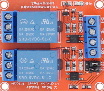
The DC 5V 2-Channel Relay is an electronic module designed to control high-voltage devices using low-voltage signals. It features two independent relay channels, allowing users to switch two separate devices on or off. This module is commonly used in home automation, industrial control systems, and DIY electronics projects. Its ability to interface with microcontrollers like Arduino and Raspberry Pi makes it a versatile choice for hobbyists and professionals alike.
Explore Projects Built with DC 5v 2-Channel Relay


Explore Projects Built with DC 5v 2-Channel Relay
Common Applications
- Home automation (e.g., controlling lights, fans, or appliances)
- Industrial equipment control
- Robotics and IoT projects
- Motor and pump control
- Security systems (e.g., activating alarms or locks)
Technical Specifications
Key Technical Details
| Parameter | Specification |
|---|---|
| Operating Voltage | 5V DC |
| Trigger Voltage | 3.3V to 5V DC |
| Relay Channels | 2 |
| Maximum Load (AC) | 250V AC at 10A |
| Maximum Load (DC) | 30V DC at 10A |
| Isolation | Optocoupler isolation |
| Dimensions | ~50mm x 40mm x 18mm |
| Indicator LEDs | Power LED and channel status LEDs |
Pin Configuration and Descriptions
Input Pins
| Pin Name | Description |
|---|---|
| VCC | Connect to 5V DC power supply. |
| GND | Ground connection. |
| IN1 | Control signal for Relay 1. Active LOW (0V triggers the relay). |
| IN2 | Control signal for Relay 2. Active LOW (0V triggers the relay). |
Output Terminals (for each relay channel)
| Terminal Name | Description |
|---|---|
| COM | Common terminal for the relay. Connect to the power source or load. |
| NO | Normally Open terminal. Connect to the load for default OFF state. |
| NC | Normally Closed terminal. Connect to the load for default ON state. |
Usage Instructions
How to Use the Component in a Circuit
- Power the Module: Connect the VCC pin to a 5V DC power source and the GND pin to ground.
- Connect Control Signals: Use IN1 and IN2 pins to control the relays. These pins can be connected to a microcontroller's GPIO pins or any other control circuit.
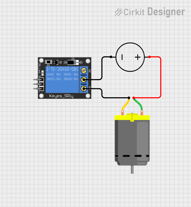
- Connect the Load:
- For devices that should remain OFF by default, connect them between the COM and NO terminals.
- For devices that should remain ON by default, connect them between the COM and NC terminals.
- Trigger the Relays: Send a LOW signal (0V) to IN1 or IN2 to activate the corresponding relay. A HIGH signal (5V) will deactivate the relay.
Important Considerations and Best Practices
- Isolation: The module uses optocouplers for isolation, ensuring safe operation when controlling high-voltage devices.
- Power Supply: Ensure the power supply can provide sufficient current for the relays (typically ~70mA per relay when active).
- Load Ratings: Do not exceed the maximum load ratings (250V AC/10A or 30V DC/10A) to avoid damage or hazards.
- Flyback Diodes: If controlling inductive loads (e.g., motors), use flyback diodes across the load to protect the relay from voltage spikes.
- Arduino Compatibility: The module is compatible with 3.3V and 5V logic levels, making it suitable for Arduino and other microcontrollers.
Example Arduino Code
// Example code to control a DC 5V 2-Channel Relay with an Arduino UNO

// Define the relay control pins
#define RELAY1 7  // Pin connected to IN1
#define RELAY2 8  // Pin connected to IN2

void setup() {
  // Set relay pins as outputs
  pinMode(RELAY1, OUTPUT);
  pinMode(RELAY2, OUTPUT);

  // Initialize relays to OFF state
  digitalWrite(RELAY1, HIGH); // HIGH = relay off
  digitalWrite(RELAY2, HIGH); // HIGH = relay off
}

void loop() {
  // Turn Relay 1 ON
  digitalWrite(RELAY1, LOW); // LOW = relay on
  delay(1000);               // Wait for 1 second

  // Turn Relay 1 OFF
  digitalWrite(RELAY1, HIGH); // HIGH = relay off
  delay(1000);                // Wait for 1 second

  // Turn Relay 2 ON
  digitalWrite(RELAY2, LOW); // LOW = relay on
  delay(1000);               // Wait for 1 second

  // Turn Relay 2 OFF
  digitalWrite(RELAY2, HIGH); // HIGH = relay off
  delay(1000);                // Wait for 1 second
}
Troubleshooting and FAQs
Common Issues and Solutions
Relays Not Activating:
- Ensure the VCC and GND pins are properly connected to a 5V power source.
- Verify that the control signals (IN1/IN2) are being set to LOW (0V) to activate the relays.
- Check the power supply's current rating; it should be sufficient to drive the relays.
Load Not Switching:
- Confirm that the load is correctly connected to the COM and NO/NC terminals.
- Verify that the load does not exceed the relay's maximum ratings.
Interference or Noise:
- Use proper grounding and shielding to minimize electrical noise.
- Add a capacitor across the relay's power supply terminals to filter noise.
Relay Stuck or Not Releasing:
- Check for mechanical damage or wear on the relay.
- For inductive loads, ensure flyback diodes are installed to prevent voltage spikes.
FAQs
Q: Can I use this module with a 3.3V microcontroller?
A: Yes, the module is compatible with 3.3V logic levels, but ensure the VCC pin is powered with 5V.
Q: Is it safe to control high-voltage AC devices with this module?
A: Yes, but always follow proper safety precautions and ensure the load does not exceed the relay's ratings.
Q: Can I control both relays simultaneously?
A: Yes, you can activate both relays at the same time by sending LOW signals to both IN1 and IN2.
Q: What happens if I reverse the VCC and GND connections?
A: Reversing the power connections can damage the module. Always double-check your wiring before powering the circuit.