Cirkit Designer Logo
Cirkit Designer
Your all-in-one circuit design IDE
Home / 
Component Documentation

How to Use AS6500: Examples, Pinouts, and Specs

Image of AS6500
Cirkit Designer LogoDesign with AS6500 in Cirkit Designer

Introduction

The AS6500 is a high-performance analog-to-digital converter (ADC) designed for precision measurement applications. It offers low power consumption, high resolution, and fast sampling rates, making it ideal for applications requiring accurate and reliable data conversion. The AS6500 is commonly used in industrial automation, medical devices, and consumer electronics, where precise signal processing is critical.

Explore Projects Built with AS6500

Use Cirkit Designer to design, explore, and prototype these projects online. Some projects support real-time simulation. Click "Open Project" to start designing instantly!
Satellite-Based Timing and Navigation System with SDR and Atomic Clock Synchronization
Image of GPS 시스템 측정 구성도_Confirm: A project utilizing AS6500 in a practical application
This circuit appears to be a complex system involving power supply management, GPS and timing synchronization, and data communication. It includes a SI-TEX G1 Satellite Compass for GPS data, an XHTF1021 Atomic Rubidium Clock for precise timing, and Ettus USRP B200 units for software-defined radio communication. Power is supplied through various SMPS units and distributed via terminal blocks and DC jacks. Data communication is facilitated by Beelink MINI S12 N95 computers, RS232 splitters, and a 1000BASE-T Media Converter for network connectivity. RF Directional Couplers are used to interface antennas with the USRP units, and the entire system is likely contained within cases for protection and organization.
Cirkit Designer LogoOpen Project in Cirkit Designer
Satellite Compass and Network-Integrated GPS Data Processing System
Image of GPS 시스템 측정 구성도_241016: A project utilizing AS6500 in a practical application
This circuit comprises a satellite compass, a mini PC, two GPS antennas, power supplies, a network switch, media converters, and an atomic rubidium clock. The satellite compass is powered by a triple output DC power supply and interfaces with an RS232 splitter for 1PPS signals. The mini PCs are connected to the USRP B200 devices via USB for data and power, and to media converters via Ethernet, which in turn connect to a network switch using fiber optic links. The antennas are connected to the USRP B200s through RF directional couplers, and the atomic clock provides a 1PPS input to the RS232 splitter.
Cirkit Designer LogoOpen Project in Cirkit Designer
Multi-Channel Load Cell Measurement System with JYS60 Amplifiers and DAQ Integration
Image of Load Cell Circuit: A project utilizing AS6500 in a practical application
This is a multi-channel load cell measurement system with several JYS60 amplifiers connected to load cells for weight or force sensing. The amplified signals are directed to a DAQ system for data capture, and power is supplied through a barrel jack. Grounding is achieved via an AdaGator Side Black component.
Cirkit Designer LogoOpen Project in Cirkit Designer
Solar-Powered Environmental Monitoring Station with GSM Reporting
Image of thesis nila po: A project utilizing AS6500 in a practical application
This is a solar-powered monitoring and control system with automatic power source selection, environmental sensing, and communication capabilities. It uses an ESP32 microcontroller to process inputs from gas, flame, and temperature sensors, and to manage outputs like an LCD display, LEDs, and a buzzer. The system can communicate via a SIM900A module and switch between solar and AC power sources using an ATS.
Cirkit Designer LogoOpen Project in Cirkit Designer

Explore Projects Built with AS6500

Use Cirkit Designer to design, explore, and prototype these projects online. Some projects support real-time simulation. Click "Open Project" to start designing instantly!
Image of GPS 시스템 측정 구성도_Confirm: A project utilizing AS6500 in a practical application
Satellite-Based Timing and Navigation System with SDR and Atomic Clock Synchronization
This circuit appears to be a complex system involving power supply management, GPS and timing synchronization, and data communication. It includes a SI-TEX G1 Satellite Compass for GPS data, an XHTF1021 Atomic Rubidium Clock for precise timing, and Ettus USRP B200 units for software-defined radio communication. Power is supplied through various SMPS units and distributed via terminal blocks and DC jacks. Data communication is facilitated by Beelink MINI S12 N95 computers, RS232 splitters, and a 1000BASE-T Media Converter for network connectivity. RF Directional Couplers are used to interface antennas with the USRP units, and the entire system is likely contained within cases for protection and organization.
Cirkit Designer LogoOpen Project in Cirkit Designer
Image of GPS 시스템 측정 구성도_241016: A project utilizing AS6500 in a practical application
Satellite Compass and Network-Integrated GPS Data Processing System
This circuit comprises a satellite compass, a mini PC, two GPS antennas, power supplies, a network switch, media converters, and an atomic rubidium clock. The satellite compass is powered by a triple output DC power supply and interfaces with an RS232 splitter for 1PPS signals. The mini PCs are connected to the USRP B200 devices via USB for data and power, and to media converters via Ethernet, which in turn connect to a network switch using fiber optic links. The antennas are connected to the USRP B200s through RF directional couplers, and the atomic clock provides a 1PPS input to the RS232 splitter.
Cirkit Designer LogoOpen Project in Cirkit Designer
Image of Load Cell Circuit: A project utilizing AS6500 in a practical application
Multi-Channel Load Cell Measurement System with JYS60 Amplifiers and DAQ Integration
This is a multi-channel load cell measurement system with several JYS60 amplifiers connected to load cells for weight or force sensing. The amplified signals are directed to a DAQ system for data capture, and power is supplied through a barrel jack. Grounding is achieved via an AdaGator Side Black component.
Cirkit Designer LogoOpen Project in Cirkit Designer
Image of thesis nila po: A project utilizing AS6500 in a practical application
Solar-Powered Environmental Monitoring Station with GSM Reporting
This is a solar-powered monitoring and control system with automatic power source selection, environmental sensing, and communication capabilities. It uses an ESP32 microcontroller to process inputs from gas, flame, and temperature sensors, and to manage outputs like an LCD display, LEDs, and a buzzer. The system can communicate via a SIM900A module and switch between solar and AC power sources using an ATS.
Cirkit Designer LogoOpen Project in Cirkit Designer

Common Applications:

  • Industrial process control and automation
  • Medical instrumentation (e.g., ECG, EEG devices)
  • Consumer electronics (e.g., audio equipment, sensors)
  • Data acquisition systems
  • Scientific measurement tools

Technical Specifications

The AS6500 is engineered to deliver exceptional performance in demanding environments. Below are its key technical specifications:

Parameter Value
Resolution 16-bit
Sampling Rate Up to 1 MSPS (Mega Samples Per Second)
Input Voltage Range 0 V to 5 V
Power Supply Voltage 2.7 V to 5.5 V
Power Consumption 10 mW (typical)
Input Channels 2 (differential) or 4 (single-ended)
Communication Interface SPI
Operating Temperature -40°C to +85°C
Package Type TSSOP-16

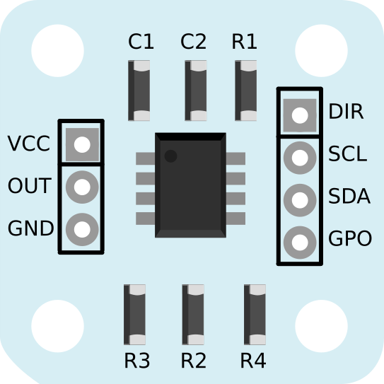
Pin Configuration and Descriptions

The AS6500 comes in a 16-pin TSSOP package. Below is the pinout and description:

Pin Number Pin Name Description
1 VDD Positive power supply (2.7 V to 5.5 V)
2 GND Ground
3 IN+ Positive input for differential signal
4 IN- Negative input for differential signal
5 REF+ Positive reference voltage input
6 REF- Negative reference voltage input
7 SCLK SPI clock input
8 MISO SPI data output (Master In Slave Out)
9 MOSI SPI data input (Master Out Slave In)
10 CS Chip select (active low)
11 DRDY Data ready output (indicates conversion complete)
12 RESET Reset input (active low)
13 NC No connection
14 NC No connection
15 VREF Reference voltage for ADC
16 AGND Analog ground

Usage Instructions

How to Use the AS6500 in a Circuit

  1. Power Supply: Connect the VDD pin to a stable power source (2.7 V to 5.5 V) and GND to ground.
  2. Input Signal: For differential input, connect the signal to IN+ and IN-. For single-ended input, connect the signal to IN+ and ground IN-.
  3. Reference Voltage: Provide a stable reference voltage to REF+ and REF-. Ensure the reference voltage is within the specified range.
  4. SPI Communication: Connect the SCLK, MISO, MOSI, and CS pins to the corresponding SPI pins of your microcontroller.
  5. Data Ready Signal: Monitor the DRDY pin to detect when a conversion is complete.
  6. Reset: Use the RESET pin to initialize the ADC if needed.

Important Considerations and Best Practices

  • Use decoupling capacitors (e.g., 0.1 µF and 10 µF) close to the VDD and GND pins to reduce noise.
  • Ensure the reference voltage is stable and free from noise for accurate conversions.
  • Keep the analog and digital grounds separate to minimize interference.
  • Use shielded cables for input signals in noisy environments.
  • Avoid exceeding the input voltage range to prevent damage to the ADC.

Example Code for Arduino UNO

Below is an example of how to interface the AS6500 with an Arduino UNO using SPI:

#include <SPI.h>

// Pin definitions
const int CS_PIN = 10;  // Chip select pin
const int DRDY_PIN = 2; // Data ready pin

void setup() {
  // Initialize SPI
  SPI.begin();
  SPI.setClockDivider(SPI_CLOCK_DIV16); // Set SPI clock speed
  SPI.setDataMode(SPI_MODE0);           // Set SPI mode
  pinMode(CS_PIN, OUTPUT);
  pinMode(DRDY_PIN, INPUT);
  digitalWrite(CS_PIN, HIGH);           // Set CS high (inactive)

  Serial.begin(9600);                   // Initialize serial communication
}

void loop() {
  if (digitalRead(DRDY_PIN) == LOW) {   // Check if data is ready
    digitalWrite(CS_PIN, LOW);          // Select the AS6500
    byte highByte = SPI.transfer(0x00); // Read high byte of ADC data
    byte lowByte = SPI.transfer(0x00);  // Read low byte of ADC data
    digitalWrite(CS_PIN, HIGH);         // Deselect the AS6500

    // Combine high and low bytes into a 16-bit value
    int adcValue = (highByte << 8) | lowByte;

    // Print the ADC value
    Serial.println(adcValue);
  }
}

Troubleshooting and FAQs

Common Issues and Solutions

  1. No Data Output:

    • Ensure the SPI connections (SCLK, MISO, MOSI, CS) are correct.
    • Verify that the DRDY pin is being monitored correctly.
    • Check the power supply and reference voltage.
  2. Inaccurate Readings:

    • Ensure the input signal is within the specified voltage range.
    • Verify the stability of the reference voltage.
    • Minimize noise by using proper grounding and shielding techniques.
  3. Device Not Responding:

    • Check the RESET pin to ensure the device is not held in reset state.
    • Verify the SPI clock speed and mode settings.

FAQs

Q: Can the AS6500 be used with 3.3 V systems?
A: Yes, the AS6500 operates with a power supply voltage as low as 2.7 V, making it compatible with 3.3 V systems.

Q: What is the maximum sampling rate of the AS6500?
A: The AS6500 supports a maximum sampling rate of 1 MSPS.

Q: How do I handle unused input channels?
A: For unused input channels, connect them to ground to avoid floating inputs and noise interference.

Q: Can I use the AS6500 with a 5 V Arduino?
A: Yes, the AS6500 is compatible with 5 V systems, including 5 V Arduino boards. Ensure proper SPI connections.