
How to Use Adafruit CAN Bus BFF: Examples, Pinouts, and Specs
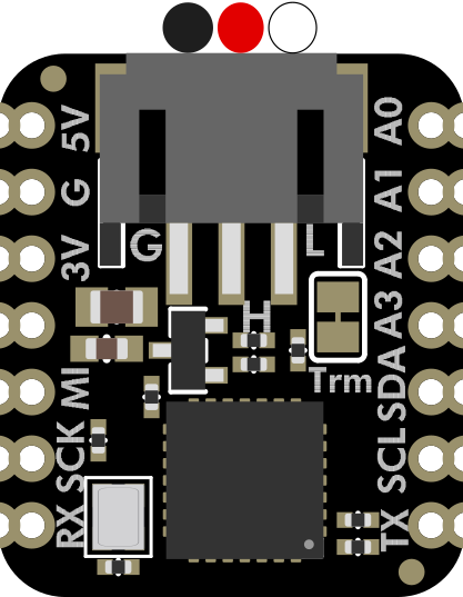
 Design with Adafruit CAN Bus BFF in Cirkit Designer
Introduction
The Adafruit CAN Bus BFF (Manufacturer Part ID: 5877) is a compact breakout board designed to simplify interfacing with CAN (Controller Area Network) devices. It provides an easy and reliable way to connect microcontrollers, such as Arduino boards, to the CAN bus, enabling communication with automotive, industrial, and embedded systems.
The CAN Bus BFF is ideal for applications requiring robust communication between multiple devices, such as vehicle diagnostics, industrial automation, and robotics. Its small form factor and compatibility with popular microcontrollers make it a versatile choice for both hobbyists and professionals.
Explore Projects Built with Adafruit CAN Bus BFF
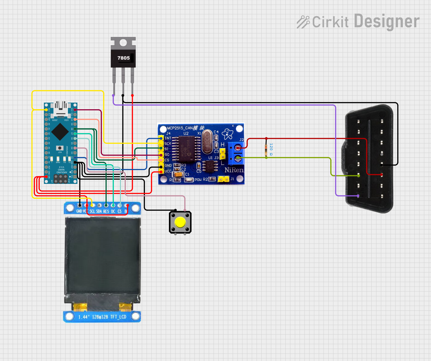 Open Project in Cirkit Designer
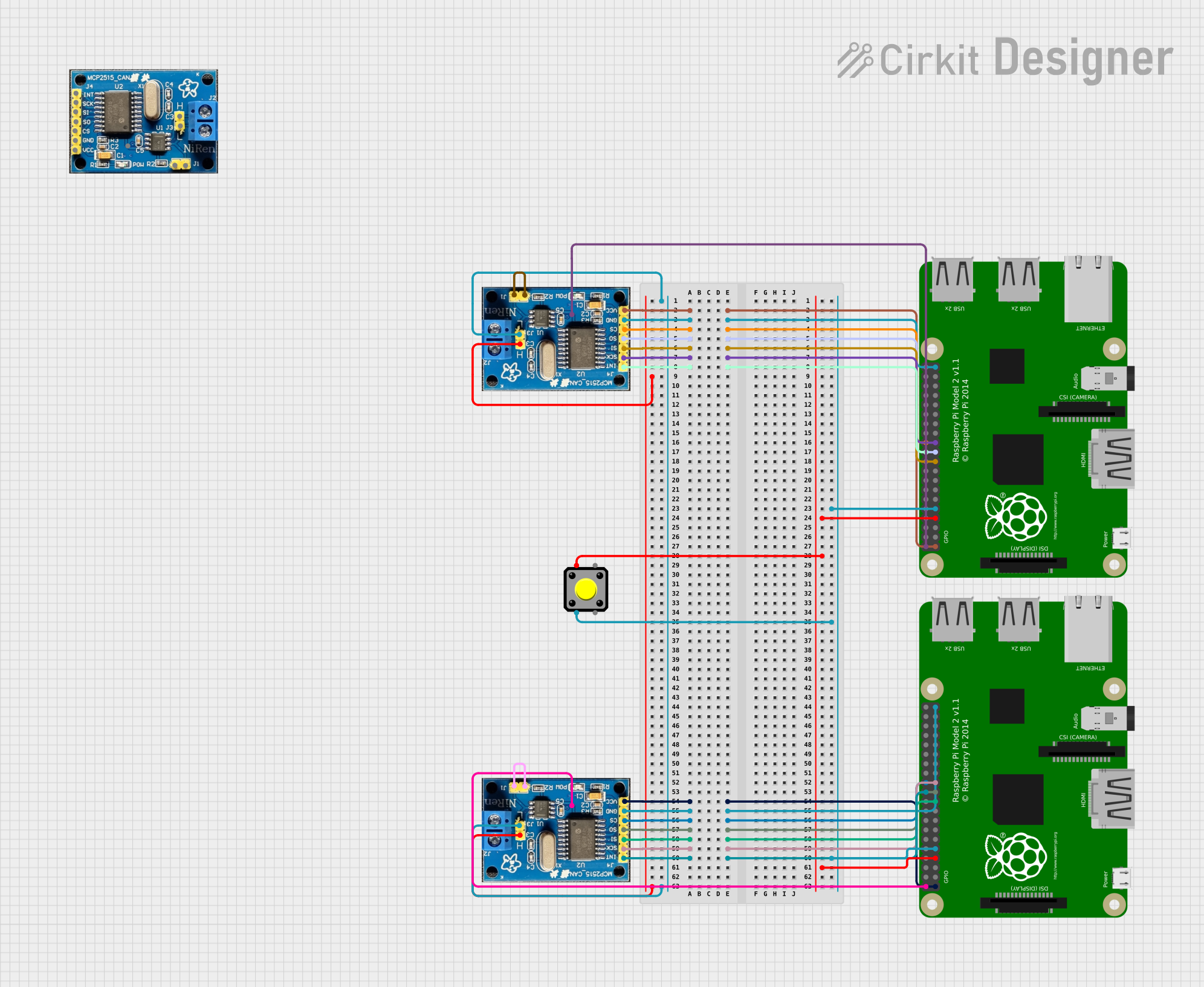 Open Project in Cirkit Designer
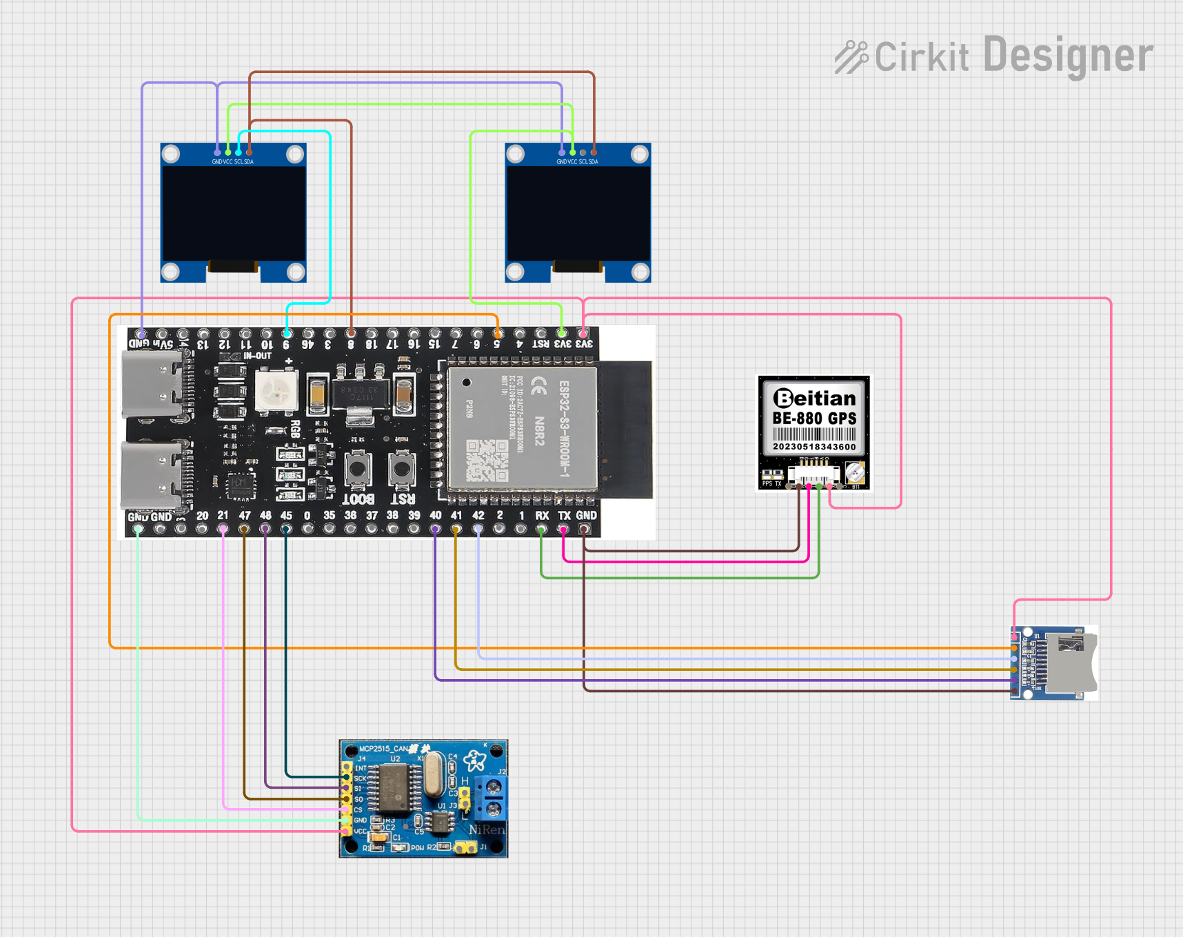 Open Project in Cirkit Designer
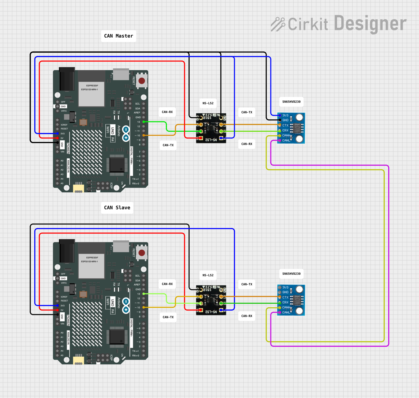 Open Project in Cirkit Designer
Explore Projects Built with Adafruit CAN Bus BFF
Open Project in Cirkit DesignerOpen Project in Cirkit DesignerOpen Project in Cirkit DesignerOpen Project in Cirkit DesignerTechnical Specifications
The Adafruit CAN Bus BFF is built around the MCP2515 CAN controller and the TJA1051 CAN transceiver, ensuring reliable and efficient communication. Below are the key technical details:
General Specifications
- Controller IC: MCP2515 (SPI-based CAN controller)
- Transceiver IC: TJA1051 (High-speed CAN transceiver)
- Operating Voltage: 3.3V or 5V (logic level compatible)
- CAN Bus Speed: Up to 1 Mbps
- Interface: SPI (Serial Peripheral Interface)
- Dimensions: 22mm x 18mm x 3mm (excluding headers)
Pin Configuration and Descriptions
The Adafruit CAN Bus BFF has the following pinout:
| Pin Name | Type | Description |
|---|---|---|
| VIN | Power Input | Power input for the board (3.3V or 5V). |
| GND | Ground | Ground connection. |
| SCK | SPI Clock | SPI clock input for communication with the microcontroller. |
| MISO | SPI Data Out | SPI data output from the MCP2515 to the microcontroller. |
| MOSI | SPI Data In | SPI data input from the microcontroller to the MCP2515. |
| CS | Chip Select | SPI chip select pin for enabling communication with the MCP2515. |
| INT | Interrupt | Interrupt pin triggered by the MCP2515 to signal events (e.g., message received). |
| CANH | CAN High | High line of the CAN bus. |
| CANL | CAN Low | Low line of the CAN bus. |
Usage Instructions
Connecting the Adafruit CAN Bus BFF
- Power the Board: Connect the VIN pin to a 3.3V or 5V power source and the GND pin to ground.
- Connect to SPI: Wire the SCK, MISO, MOSI, and CS pins to the corresponding SPI pins on your microcontroller.
- Connect the CAN Bus: Attach the CANH and CANL pins to the CAN bus lines of your system.
- Interrupt Pin (Optional): Connect the INT pin to a GPIO pin on your microcontroller if you want to use interrupt-driven communication.
Example: Using with Arduino UNO
Below is an example of how to use the Adafruit CAN Bus BFF with an Arduino UNO. This example uses the popular MCP_CAN library.
Wiring Diagram
| Adafruit CAN Bus BFF Pin | Arduino UNO Pin |
|---|---|
| VIN | 5V |
| GND | GND |
| SCK | D13 |
| MISO | D12 |
| MOSI | D11 |
| CS | D10 |
| INT | D2 |
Arduino Code Example
#include <SPI.h>
#include <mcp_can.h>

// Define the SPI CS pin for the MCP2515
#define CAN_CS_PIN 10

// Create an instance of the MCP_CAN class
MCP_CAN CAN(CAN_CS_PIN);

void setup() {
  Serial.begin(115200);
  while (!Serial);

  // Initialize the MCP2515 CAN controller at 500 kbps
  if (CAN.begin(MCP_ANY, CAN_500KBPS, MCP_8MHZ) == CAN_OK) {
    Serial.println("CAN Bus initialized successfully!");
  } else {
    Serial.println("Error initializing CAN Bus.");
    while (1);
  }

  // Set the CAN controller to normal mode
  CAN.setMode(MCP_NORMAL);
  Serial.println("CAN Bus is now in normal mode.");
}

void loop() {
  // Example: Send a CAN message
  byte data[8] = {0x01, 0x02, 0x03, 0x04, 0x05, 0x06, 0x07, 0x08};
  if (CAN.sendMsgBuf(0x100, 0, 8, data) == CAN_OK) {
    Serial.println("Message sent successfully!");
  } else {
    Serial.println("Error sending message.");
  }

  delay(1000); // Wait 1 second before sending the next message
}
Best Practices
- Use proper termination resistors (typically 120Ω) at both ends of the CAN bus to ensure signal integrity.
- Keep the CANH and CANL lines twisted to reduce electromagnetic interference (EMI).
- Ensure that all devices on the CAN bus operate at the same baud rate.
Troubleshooting and FAQs
Common Issues
CAN Bus Initialization Fails
- Cause: Incorrect wiring or mismatched baud rate.
- Solution: Double-check the wiring and ensure all devices on the CAN bus use the same baud rate.
No Communication on the CAN Bus
- Cause: Missing termination resistors or incorrect CANH/CANL connections.
- Solution: Verify that 120Ω termination resistors are present at both ends of the CAN bus and that CANH and CANL are correctly connected.
Interrupt Pin Not Working
- Cause: INT pin not connected or not configured in the code.
- Solution: Ensure the INT pin is connected to a GPIO pin on the microcontroller and properly configured in the code.
FAQs
Can I use the Adafruit CAN Bus BFF with 3.3V microcontrollers? Yes, the board is compatible with both 3.3V and 5V logic levels.
What is the maximum length of the CAN bus? The maximum length depends on the baud rate. For example, at 1 Mbps, the maximum length is approximately 40 meters.
Does the board include termination resistors? No, you need to add external 120Ω resistors at both ends of the CAN bus.
This concludes the documentation for the Adafruit CAN Bus BFF. For further assistance, refer to the official Adafruit documentation or community forums.