How to Use PIC16F877A: Examples, Pinouts, and Specs
Introduction
The PIC16F877A is an 8-bit microcontroller manufactured by Microchip Technology. It is a highly versatile and widely used microcontroller in embedded systems, offering a rich set of features such as 368 bytes of RAM, 256 bytes of EEPROM, and a 14-bit instruction set. With its 40-pin configuration, it provides ample I/O options, making it suitable for a variety of applications.
Explore Projects Built with PIC16F877A


Explore Projects Built with PIC16F877A
Common Applications and Use Cases
- Home automation systems
- Industrial control systems
- Robotics and motor control
- Data acquisition systems
- Educational projects and prototyping
Technical Specifications
Below are the key technical details of the PIC16F877A microcontroller:
| Parameter | Value |
|---|---|
| Manufacturer | Microchip Technology |
| Part Number | PIC16F877A |
| Architecture | 8-bit |
| Program Memory (Flash) | 14 KB |
| Data Memory (RAM) | 368 bytes |
| EEPROM | 256 bytes |
| Instruction Set | 14-bit |
| Operating Voltage | 2.0V to 5.5V |
| Clock Speed | Up to 20 MHz |
| I/O Pins | 33 |
| Timers | 3 (Timer0, Timer1, Timer2) |
| ADC Channels | 8 (10-bit resolution) |
| Communication Interfaces | UART, SPI, I2C |
| Package Types | DIP-40, PLCC-44, TQFP-44 |
Pin Configuration and Descriptions
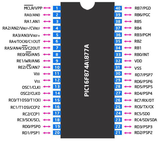
The PIC16F877A has 40 pins, each with specific functions. Below is a summary of the pin configuration:
| Pin Number | Pin Name | Description |
|---|---|---|
| 1 | MCLR/VPP | Master Clear (Reset) input or programming voltage |
| 2-7 | RA0-RA5 | Port A: Analog/Digital I/O pins |
| 8 | VSS | Ground |
| 9-10 | OSC1/OSC2 | Oscillator input/output |
| 11-18 | RB0-RB7 | Port B: Digital I/O pins |
| 19 | VDD | Positive supply voltage |
| 20-27 | RC0-RC7 | Port C: Digital I/O pins |
| 28-33 | RD0-RD7 | Port D: Digital I/O pins |
| 34-40 | RE0-RE2, VSS, VDD | Port E: Digital I/O pins, Ground, Power Supply |
Usage Instructions
How to Use the PIC16F877A in a Circuit
- Power Supply: Connect the VDD pin to a 5V power source and the VSS pin to ground.
- Oscillator: Connect an external crystal oscillator (e.g., 20 MHz) between OSC1 and OSC2 pins, along with appropriate capacitors.
- Reset: Connect a pull-up resistor (typically 10kΩ) to the MCLR pin for proper reset functionality.
- I/O Pins: Configure the I/O pins (RA, RB, RC, RD, RE) as input or output in the software, depending on your application.
- Programming: Use an ICSP (In-Circuit Serial Programming) tool to load your program into the microcontroller.
Important Considerations and Best Practices
- Use decoupling capacitors (e.g., 0.1 µF) near the power supply pins to reduce noise.
- Ensure proper grounding to avoid signal interference.
- When using ADC channels, connect a reference voltage to the VREF+ pin for accurate conversions.
- Avoid leaving unused pins floating; connect them to ground or configure them as outputs.
Example Code for Arduino UNO Integration
The PIC16F877A can communicate with an Arduino UNO via UART. Below is an example code for sending data from the Arduino to the PIC16F877A:
Arduino Code:
void setup() {
  Serial.begin(9600); // Initialize UART communication at 9600 baud rate
}

void loop() {
  Serial.println("Hello, PIC16F877A!"); // Send data to the PIC16F877A
  delay(1000); // Wait for 1 second
}
PIC16F877A Code (Using MPLAB XC8):
#include <xc.h>

// Configuration bits
#pragma config FOSC = HS        // High-speed oscillator
#pragma config WDTE = OFF       // Watchdog Timer disabled
#pragma config PWRTE = ON       // Power-up Timer enabled
#pragma config BOREN = ON       // Brown-out Reset enabled
#pragma config LVP = OFF        // Low-Voltage Programming disabled
#pragma config CPD = OFF        // Data EEPROM Memory Code Protection disabled
#pragma config WRT = OFF        // Flash Program Memory Write Protection disabled
#pragma config CP = OFF         // Flash Program Memory Code Protection disabled

#define _XTAL_FREQ 20000000     // Define the oscillator frequency (20 MHz)

void UART_Init() {
    TRISC6 = 0; // TX pin as output
    TRISC7 = 1; // RX pin as input
    SPBRG = 31; // Baud rate = 9600 for 20 MHz clock
    TXEN = 1;   // Enable transmission
    SPEN = 1;   // Enable serial port
}

void main() {
    UART_Init(); // Initialize UART
    while (1) {
        if (RCIF) { // Check if data is received
            char received = RCREG; // Read received data
            // Process the received data (e.g., toggle an LED)
        }
    }
}
Troubleshooting and FAQs
Common Issues and Solutions
Microcontroller Not Responding
- Ensure the power supply voltage is within the operating range (2.0V to 5.5V).
- Verify the oscillator circuit connections and component values.
Program Not Uploading
- Check the ICSP connections and ensure the programmer is compatible with the PIC16F877A.
- Verify that the MCLR pin is connected to the programming voltage.
Incorrect ADC Readings
- Ensure the analog input voltage is within the range of 0V to VREF+.
- Use a stable reference voltage and avoid noise on the analog input pins.
UART Communication Issues
- Verify that the baud rate settings match between the PIC16F877A and the external device.
- Check the TX and RX pin connections.
FAQs
Q: Can the PIC16F877A operate without an external oscillator?
A: Yes, it can operate using its internal RC oscillator, but an external crystal oscillator is recommended for better accuracy.
Q: How do I protect the microcontroller from voltage spikes?
A: Use a voltage regulator and transient voltage suppression (TVS) diodes to protect the microcontroller.
Q: Can I use the PIC16F877A for low-power applications?
A: Yes, the PIC16F877A supports low-power modes such as Sleep mode to reduce power consumption.
Q: What is the maximum clock speed of the PIC16F877A?
A: The maximum clock speed is 20 MHz when using an external oscillator.