Cirkit Designer Logo
Cirkit Designer
Your all-in-one circuit design IDE
Home / 
Component Documentation

How to Use TPS 61023: Examples, Pinouts, and Specs

Image of TPS 61023
Cirkit Designer LogoDesign with TPS 61023 in Cirkit Designer

Introduction

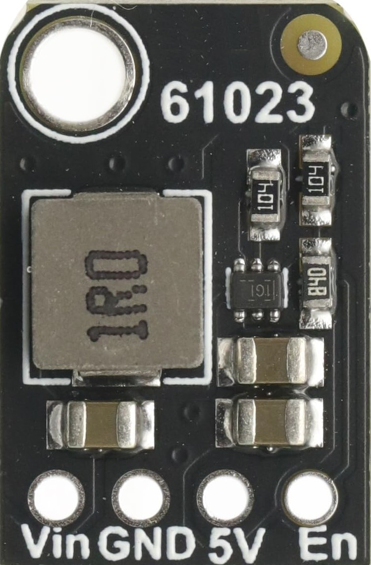
The TPS 61023 is a high-efficiency step-up (boost) DC-DC converter designed to provide a regulated output voltage from a lower input voltage. It is ideal for applications requiring efficient power conversion, such as battery-powered devices, portable electronics, and IoT systems. With its wide input voltage range, adjustable output voltage, and minimal external component requirements, the TPS 61023 offers a compact and reliable solution for power management.

Explore Projects Built with TPS 61023

Use Cirkit Designer to design, explore, and prototype these projects online. Some projects support real-time simulation. Click "Open Project" to start designing instantly!
ESP32 and SIM800L-Based Smart Power Monitor with Voltage Sensors
Image of Generator state monitor: A project utilizing TPS 61023 in a practical application
This circuit is a power monitoring and control system that uses an ESP32 microcontroller to read voltage and current values from multiple sensors, calculate power consumption, and send notifications via a SIM800L GSM module. It also includes a TP4056 module for battery charging, a step-up boost converter, and an AC-DC converter to power the system, with the ability to control lights through a relay based on SMS commands.
Cirkit Designer LogoOpen Project in Cirkit Designer
ESP32-Based Environmental Monitoring System with Nokia 5110 LCD and Multiple Sensors
Image of MONITORING STATION WATER QUALITY : A project utilizing TPS 61023 in a practical application
This circuit is a solar-powered environmental monitoring system that uses an ESP32 microcontroller to interface with various sensors (temperature, turbidity, TDS, pH, dissolved oxygen, electrical conductivity, and ORP) and a GPS module. The system charges a 18650 Li-Ion battery via a TP4056 module connected to a solar panel, and displays data on a Nokia 5110 LCD.
Cirkit Designer LogoOpen Project in Cirkit Designer
Satellite-Based Timing and Navigation System with SDR and Atomic Clock Synchronization
Image of GPS 시스템 측정 구성도_Confirm: A project utilizing TPS 61023 in a practical application
This circuit appears to be a complex system involving power supply management, GPS and timing synchronization, and data communication. It includes a SI-TEX G1 Satellite Compass for GPS data, an XHTF1021 Atomic Rubidium Clock for precise timing, and Ettus USRP B200 units for software-defined radio communication. Power is supplied through various SMPS units and distributed via terminal blocks and DC jacks. Data communication is facilitated by Beelink MINI S12 N95 computers, RS232 splitters, and a 1000BASE-T Media Converter for network connectivity. RF Directional Couplers are used to interface antennas with the USRP units, and the entire system is likely contained within cases for protection and organization.
Cirkit Designer LogoOpen Project in Cirkit Designer
Modular Power Distribution System with Multiple SMPS Units and 120V Outlet
Image of Cellion-Tesla: A project utilizing TPS 61023 in a practical application
This circuit is designed to convert 240V AC power to both 12V and 24V DC outputs using multiple SMPS units. Terminal blocks are used to organize and distribute the power, while a 120V outlet provides additional AC power access. The circuit is likely used for powering various electronic devices that require different voltage levels.
Cirkit Designer LogoOpen Project in Cirkit Designer

Explore Projects Built with TPS 61023

Use Cirkit Designer to design, explore, and prototype these projects online. Some projects support real-time simulation. Click "Open Project" to start designing instantly!
Image of Generator state monitor: A project utilizing TPS 61023 in a practical application
ESP32 and SIM800L-Based Smart Power Monitor with Voltage Sensors
This circuit is a power monitoring and control system that uses an ESP32 microcontroller to read voltage and current values from multiple sensors, calculate power consumption, and send notifications via a SIM800L GSM module. It also includes a TP4056 module for battery charging, a step-up boost converter, and an AC-DC converter to power the system, with the ability to control lights through a relay based on SMS commands.
Cirkit Designer LogoOpen Project in Cirkit Designer
Image of MONITORING STATION WATER QUALITY : A project utilizing TPS 61023 in a practical application
ESP32-Based Environmental Monitoring System with Nokia 5110 LCD and Multiple Sensors
This circuit is a solar-powered environmental monitoring system that uses an ESP32 microcontroller to interface with various sensors (temperature, turbidity, TDS, pH, dissolved oxygen, electrical conductivity, and ORP) and a GPS module. The system charges a 18650 Li-Ion battery via a TP4056 module connected to a solar panel, and displays data on a Nokia 5110 LCD.
Cirkit Designer LogoOpen Project in Cirkit Designer
Image of GPS 시스템 측정 구성도_Confirm: A project utilizing TPS 61023 in a practical application
Satellite-Based Timing and Navigation System with SDR and Atomic Clock Synchronization
This circuit appears to be a complex system involving power supply management, GPS and timing synchronization, and data communication. It includes a SI-TEX G1 Satellite Compass for GPS data, an XHTF1021 Atomic Rubidium Clock for precise timing, and Ettus USRP B200 units for software-defined radio communication. Power is supplied through various SMPS units and distributed via terminal blocks and DC jacks. Data communication is facilitated by Beelink MINI S12 N95 computers, RS232 splitters, and a 1000BASE-T Media Converter for network connectivity. RF Directional Couplers are used to interface antennas with the USRP units, and the entire system is likely contained within cases for protection and organization.
Cirkit Designer LogoOpen Project in Cirkit Designer
Image of Cellion-Tesla: A project utilizing TPS 61023 in a practical application
Modular Power Distribution System with Multiple SMPS Units and 120V Outlet
This circuit is designed to convert 240V AC power to both 12V and 24V DC outputs using multiple SMPS units. Terminal blocks are used to organize and distribute the power, while a 120V outlet provides additional AC power access. The circuit is likely used for powering various electronic devices that require different voltage levels.
Cirkit Designer LogoOpen Project in Cirkit Designer

Common Applications

  • Battery-powered devices (e.g., wearables, medical devices)
  • Portable electronics
  • IoT devices and sensors
  • LED drivers
  • Powering microcontrollers and low-power systems

Technical Specifications

Key Specifications

Parameter Value
Input Voltage Range 0.5 V to 5.5 V
Output Voltage Range 1.8 V to 5.5 V (adjustable)
Maximum Output Current Up to 2 A (depending on input/output conditions)
Efficiency Up to 90%
Switching Frequency 2.4 MHz
Quiescent Current (Iq) 0.5 µA (typical)
Package Type 2.0 mm × 1.5 mm WSON-6

Pin Configuration and Descriptions

The TPS 61023 is available in a 6-pin WSON package. Below is the pinout and description:

Pin Number Pin Name Description
1 SW Switch pin. Connect to the inductor and diode.
2 GND Ground pin. Connect to system ground.
3 FB Feedback pin. Connect to a resistor divider to set the output voltage.
4 EN Enable pin. Drive high to enable the device, low to disable it.
5 VIN Input voltage pin. Connect to the input power source.
6 VOUT Output voltage pin. Connect to the output capacitor and load.

Usage Instructions

How to Use the TPS 61023 in a Circuit

  1. Input and Output Capacitors:

    • Use low-ESR ceramic capacitors for both input and output to ensure stable operation.
    • Typical values: 10 µF for input and 22 µF for output.
  2. Inductor Selection:

    • Choose an inductor with a saturation current higher than the peak current of the TPS 61023.
    • Typical inductance value: 1 µH to 2.2 µH.
  3. Setting the Output Voltage:

    • Use a resistor divider connected to the FB pin to set the desired output voltage.
    • The output voltage is determined by the formula:
      [ V_{OUT} = V_{FB} \times \left(1 + \frac{R_1}{R_2}\right) ]
      where ( V_{FB} ) is 0.8 V (reference voltage).
  4. Enable Pin:

    • Drive the EN pin high (logic level > 1.2 V) to enable the device.
    • Drive it low (< 0.4 V) to disable the device.
  5. Thermal Considerations:

    • Ensure proper PCB layout with adequate thermal vias to dissipate heat.
    • Place the input and output capacitors close to the device to minimize noise.

Example Circuit

Below is a typical application circuit for the TPS 61023:

VIN ----+----[10 µF]----+---- VIN (Pin 5)
        |               |
       [Inductor]       |
        |               |
       SW (Pin 1)       |
        |               |
       [Diode]          |
        |               |
       +----[22 µF]---- VOUT (Pin 6)
        |
       FB (Pin 3) <-- Resistor Divider (R1, R2)
        |
       EN (Pin 4) <-- Enable Signal
        |
       GND (Pin 2) ---- System Ground

Arduino UNO Example Code

The TPS 61023 can be used to power an Arduino UNO from a low-voltage source. Below is an example code to toggle the EN pin using a digital output pin:

// Define the pin connected to the EN pin of TPS 61023
const int enablePin = 7;

void setup() {
  // Set the enable pin as an output
  pinMode(enablePin, OUTPUT);

  // Enable the TPS 61023 by setting the pin HIGH
  digitalWrite(enablePin, HIGH);
}

void loop() {
  // Keep the TPS 61023 enabled
  delay(1000);

  // Optional: Disable the TPS 61023 for power-saving
  // Uncomment the lines below to toggle the enable pin
  /*
  digitalWrite(enablePin, LOW); // Disable the TPS 61023
  delay(1000);                  // Wait for 1 second
  digitalWrite(enablePin, HIGH); // Re-enable the TPS 61023
  */
}

Troubleshooting and FAQs

Common Issues and Solutions

  1. Output Voltage is Incorrect:

    • Cause: Incorrect resistor divider values on the FB pin.
    • Solution: Verify the resistor values and recalculate using the output voltage formula.
  2. Device Overheating:

    • Cause: Insufficient thermal dissipation or excessive load current.
    • Solution: Improve PCB layout with thermal vias and ensure the load current is within specifications.
  3. No Output Voltage:

    • Cause: EN pin is not driven high or input voltage is too low.
    • Solution: Check the EN pin voltage and ensure the input voltage is within the specified range.
  4. High Noise or Ripple:

    • Cause: Poor capacitor selection or layout issues.
    • Solution: Use low-ESR ceramic capacitors and minimize trace lengths between components.

FAQs

Q1: Can the TPS 61023 operate with a single AA battery?
A1: Yes, the TPS 61023 can operate with input voltages as low as 0.5 V, making it suitable for single-cell battery applications.

Q2: What is the maximum output current the TPS 61023 can provide?
A2: The maximum output current depends on the input voltage and output voltage. Refer to the datasheet for detailed current capability under specific conditions.

Q3: How do I calculate the inductor value?
A3: Use the recommended range of 1 µH to 2.2 µH. For detailed calculations, refer to the datasheet's design guidelines.

Q4: Can I use the TPS 61023 to power a 5 V device from a 3.3 V source?
A4: Yes, the TPS 61023 can step up a 3.3 V input to a 5 V output, provided the load current is within the device's capability.


This concludes the documentation for the TPS 61023. For further details, refer to the official datasheet and application notes.