
How to Use Grove Light Sensor: Examples, Pinouts, and Specs
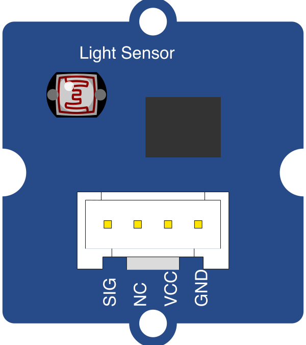
 Design with Grove Light Sensor in Cirkit Designer
Introduction
The Grove Light Sensor, manufactured by Seeed Studio, is a versatile and easy-to-use sensor designed to measure ambient light intensity. It converts light levels into an electrical signal, making it ideal for applications that require light detection and measurement. The sensor is based on a photodiode and operational amplifier, ensuring accurate and reliable performance.
Explore Projects Built with Grove Light Sensor
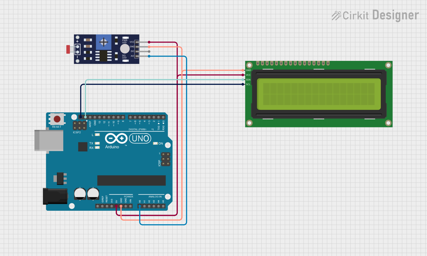 Open Project in Cirkit Designer
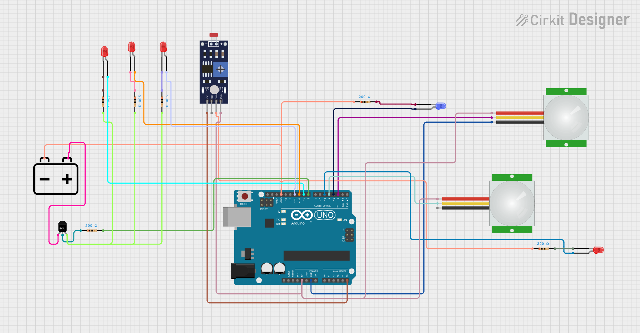 Open Project in Cirkit Designer
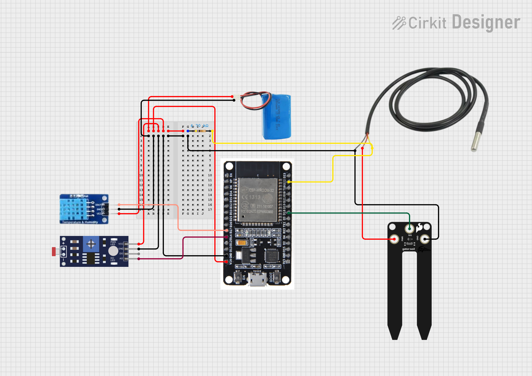 Open Project in Cirkit Designer
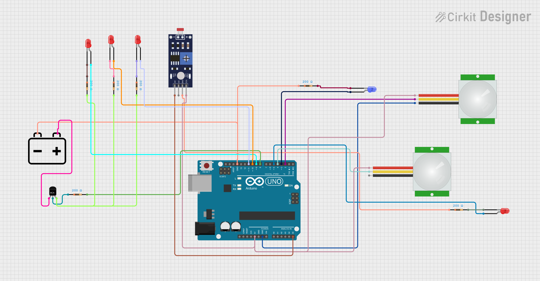 Open Project in Cirkit Designer
Explore Projects Built with Grove Light Sensor
Open Project in Cirkit DesignerOpen Project in Cirkit DesignerOpen Project in Cirkit DesignerOpen Project in Cirkit DesignerCommon Applications and Use Cases
- Automatic brightness adjustment in displays
- Smart home lighting systems
- Light-sensitive alarms and security systems
- Environmental monitoring
- Robotics and automation requiring light detection
Technical Specifications
The Grove Light Sensor is designed for simplicity and compatibility with various microcontrollers, including Arduino boards. Below are its key technical details:
Key Technical Details
- Operating Voltage: 3.3V to 5V
- Output Voltage Range: 0V to VCC
- Current Consumption: < 0.5mA
- Light Intensity Range: 0 to 1000 lux (approximate)
- Interface: Analog
- Dimensions: 20mm x 20mm
- Connector: Grove 4-pin interface
Pin Configuration and Descriptions
The Grove Light Sensor uses a 4-pin Grove connector. The pinout is as follows:
| Pin Number | Pin Name | Description |
|---|---|---|
| 1 | VCC | Power supply (3.3V or 5V) |
| 2 | GND | Ground |
| 3 | SIG | Analog signal output (light intensity) |
| 4 | NC | Not connected |
Usage Instructions
The Grove Light Sensor is straightforward to use and can be connected to a microcontroller, such as an Arduino UNO, via the Grove Base Shield or directly using jumper wires.
Connecting the Sensor
- Using a Grove Base Shield:
- Attach the Grove Base Shield to the Arduino UNO.
- Connect the Grove Light Sensor to an analog port (e.g., A0) on the Base Shield using a Grove cable.
- Without a Grove Base Shield:
- Connect the sensor's VCC pin to the Arduino's 5V pin.
- Connect the GND pin to the Arduino's GND pin.
- Connect the SIG pin to one of the Arduino's analog input pins (e.g., A0).
Sample Arduino Code
Below is an example of how to read light intensity values from the Grove Light Sensor using an Arduino UNO:
// Grove Light Sensor Example Code
// This code reads the analog value from the sensor and converts it to a light
// intensity value. The result is printed to the Serial Monitor.

const int lightSensorPin = A0; // Analog pin connected to the sensor's SIG pin

void setup() {
  Serial.begin(9600); // Initialize serial communication at 9600 baud
  pinMode(lightSensorPin, INPUT); // Set the sensor pin as input
}

void loop() {
  int sensorValue = analogRead(lightSensorPin); // Read the analog value
  float voltage = sensorValue * (5.0 / 1023.0); // Convert to voltage
  float lightIntensity = voltage * 200; // Approximate light intensity in lux
  // Note: The conversion factor (200) is an estimate and may vary.

  Serial.print("Light Intensity: ");
  Serial.print(lightIntensity);
  Serial.println(" lux");

  delay(500); // Wait for 500ms before the next reading
}
Important Considerations and Best Practices
- Power Supply: Ensure the sensor is powered within its operating voltage range (3.3V to 5V).
- Calibration: The light intensity calculation may require calibration for precise measurements, as the conversion factor can vary depending on environmental conditions.
- Placement: Avoid placing the sensor in direct sunlight for extended periods, as this may affect its lifespan.
- Signal Noise: Use short and shielded cables to minimize noise in the analog signal.
Troubleshooting and FAQs
Common Issues and Solutions
No Output or Incorrect Readings:
- Verify the connections between the sensor and the microcontroller.
- Ensure the sensor is powered correctly (3.3V or 5V).
- Check the analog pin configuration in the code.
Fluctuating or Noisy Readings:
- Use a capacitor (e.g., 0.1µF) between the SIG pin and GND to stabilize the signal.
- Ensure the sensor is not exposed to rapidly changing light conditions.
Low Sensitivity:
- Confirm that the sensor is not obstructed or covered.
- Check for any damage to the photodiode or circuit.
Frequently Asked Questions
Q: Can the Grove Light Sensor detect infrared light?
A: No, the sensor is designed to detect visible light and may not respond to infrared light.
Q: Can I use the sensor with a 3.3V microcontroller?
A: Yes, the sensor is compatible with both 3.3V and 5V systems.
Q: How do I extend the sensor's cable length?
A: Use shielded cables to reduce noise and maintain signal integrity when extending the cable length.
Q: Is the sensor waterproof?
A: No, the Grove Light Sensor is not waterproof and should be protected from moisture.
By following this documentation, you can effectively integrate the Grove Light Sensor into your projects and achieve accurate light intensity measurements.