How to Use Adafruit 0.56 inch 7-segment LED Backpack Blue: Examples, Pinouts, and Specs
Introduction
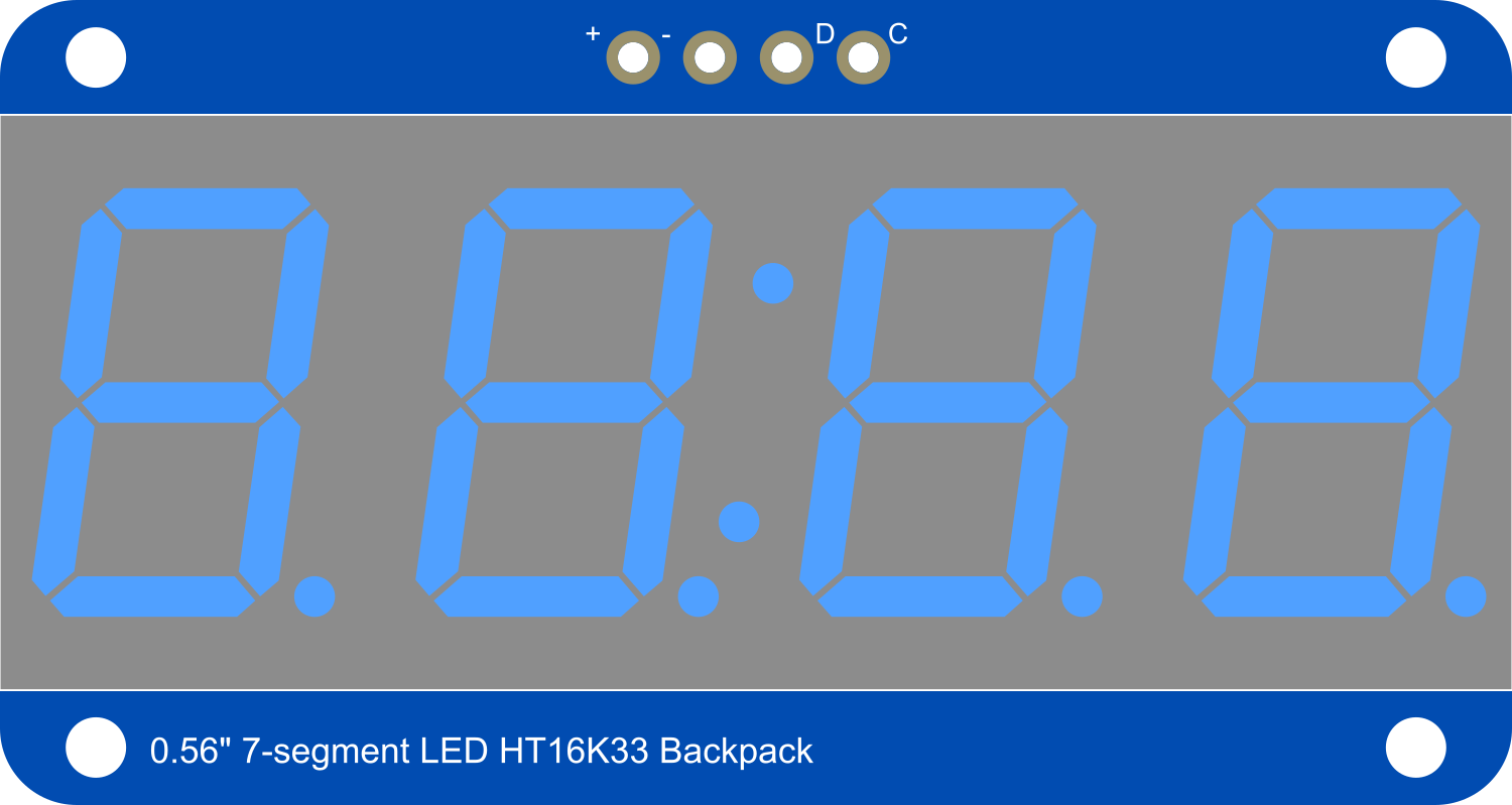
The Adafruit 0.56 inch 7-segment LED Backpack Blue is a user-friendly module designed to drive 7-segment LED displays with minimal effort and maximum efficiency. This component is ideal for projects requiring numerical output, such as clocks, counters, and readouts for sensors. The onboard controller chip handles all the complex multiplexing, allowing for simple serial communication with any microcontroller, such as an Arduino UNO.
Explore Projects Built with Adafruit 0.56 inch 7-segment LED Backpack Blue
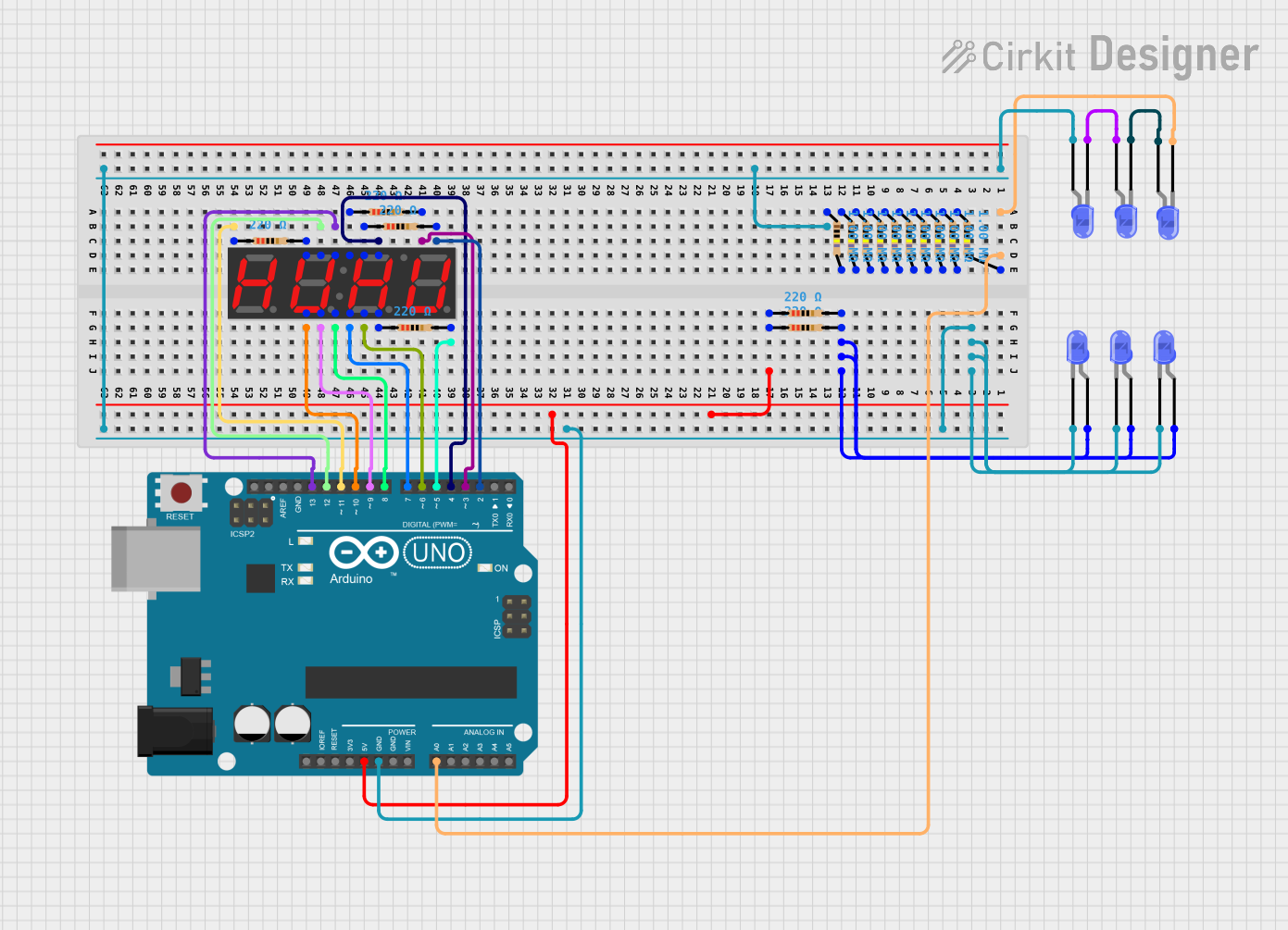
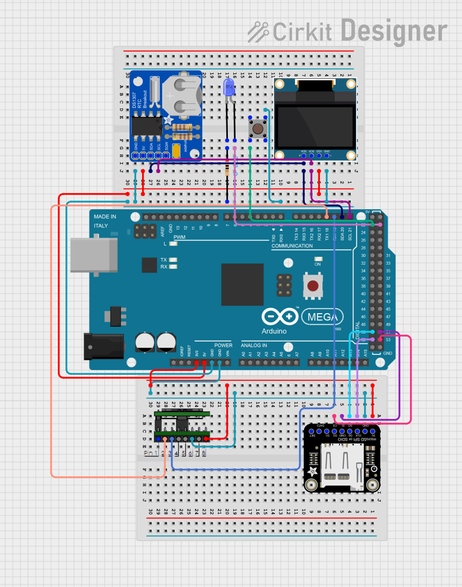

Explore Projects Built with Adafruit 0.56 inch 7-segment LED Backpack Blue
Common Applications and Use Cases
- Digital clocks and timers
- Counter displays
- Temperature readouts
- Scoreboards
- Simple calculators
Technical Specifications
Key Technical Details
- Display Color: Blue
- Digit Height: 0.56 inches
- Operating Voltage: 5V
- Interface: I2C
- I2C Addresses: 0x70 (default) - 0x77 (selectable with solder jumpers)
- Forward Current: 120 mA (max)
Pin Configuration and Descriptions
| Pin | Function | Description |
|---|---|---|
| GND | Ground | Connect to system ground |
| VCC | Power | Connect to 5V power supply |
| SDA | Data | I2C data line |
| SCL | Clock | I2C clock line |
Usage Instructions
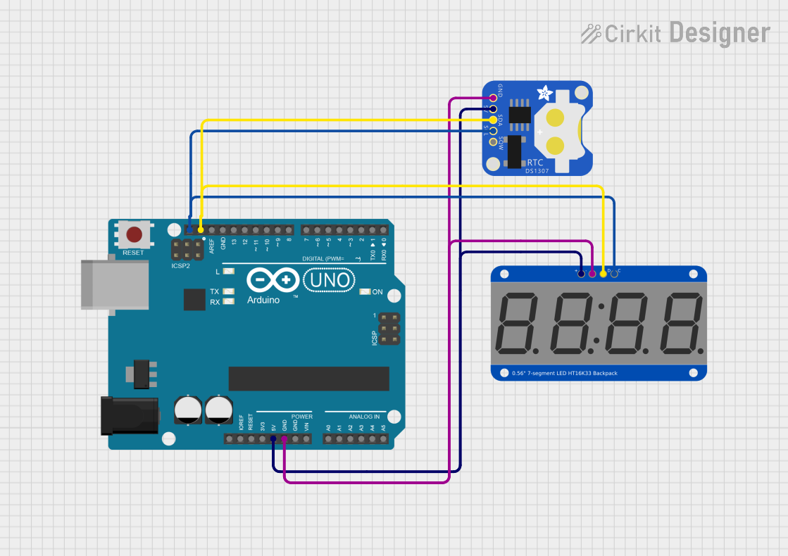
Interfacing with a Circuit
- Connect the
GNDpin to the ground of your power supply. - Connect the
VCCpin to a 5V output from your power supply. - Connect the
SDAandSCLpins to the corresponding I2C pins on your microcontroller (e.g., A4 and A5 on an Arduino UNO).
Important Considerations and Best Practices
- Ensure that the power supply does not exceed 5V as it may damage the module.
- Use pull-up resistors on the I2C lines if your microcontroller does not have built-in pull-ups.
- To change the I2C address, solder the address jumpers on the back of the PCB.
- Avoid exposing the display to direct sunlight for extended periods to prevent damage.
Example Code for Arduino UNO
#include <Wire.h>
#include <Adafruit_GFX.h>
#include <Adafruit_LEDBackpack.h>

Adafruit_7segment matrix = Adafruit_7segment();

void setup() {
  matrix.begin(0x70); // Initialize the display with its I2C address
}

void loop() {
  matrix.print(1234, DEC); // Display the number 1234
  matrix.writeDisplay();   // Refresh the display with new data
  delay(500);              // Wait for half a second
}
Troubleshooting and FAQs
Common Issues
- Display not lighting up: Ensure that the power connections are correct and secure. Check that the I2C address is correctly set and that the microcontroller is properly communicating with the display.
- Garbled or incorrect output: Verify that the code uploaded to the microcontroller is correct. Check for loose connections or solder bridges on the I2C lines.
- Dim display: Confirm that the power supply is providing a stable 5V. If using multiple displays, ensure that the power supply can handle the cumulative current draw.
Solutions and Tips for Troubleshooting
- Double-check wiring, especially the I2C connections.
- Use the
i2cdetectutility or similar to confirm the device's address on the I2C bus. - Review and compile the example code to ensure there are no syntax or logical errors.
- If multiple devices are on the I2C bus, ensure that each device has a unique address.
FAQs
Q: Can I use this display with a 3.3V system? A: While the display is designed for 5V, it may work at 3.3V with reduced brightness. However, this is not officially supported, and level shifting for I2C lines may be necessary.
Q: How do I change the I2C address? A: Solder the address jumpers on the back of the PCB to configure the address between 0x70 and 0x77.
Q: Can I control multiple displays with one microcontroller? A: Yes, you can control up to 8 displays by setting a unique I2C address for each one.
Q: Is it possible to display letters as well as numbers? A: The 7-segment display is primarily designed for numbers, but some letters can be approximated. Refer to the Adafruit GFX library for custom character support.
For further assistance, consult the Adafruit support forums or the product's FAQ page.