How to Use Led Wire Strip: Examples, Pinouts, and Specs

Introduction
LED wire strips are flexible circuit boards embedded with light-emitting diodes (LEDs) that emit bright, energy-efficient light. These strips are versatile and can be cut to size, making them ideal for a wide range of applications, including decorative lighting, task lighting, and accent lighting. They are commonly used in homes, offices, vehicles, and DIY projects due to their ease of installation and customization.
Explore Projects Built with Led Wire Strip
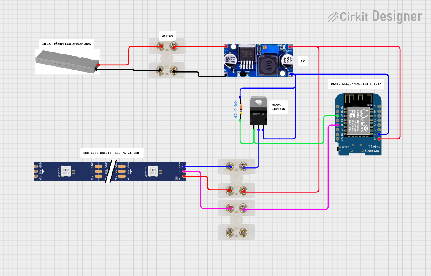
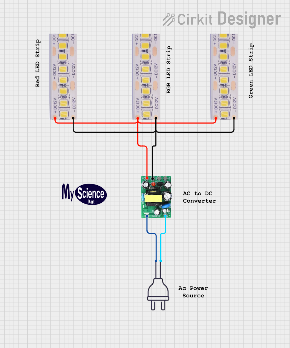
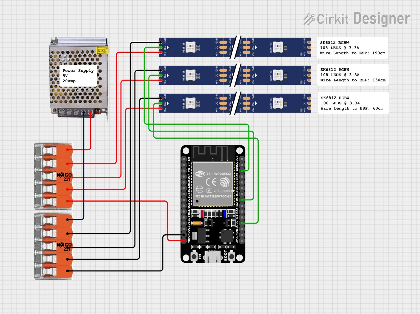
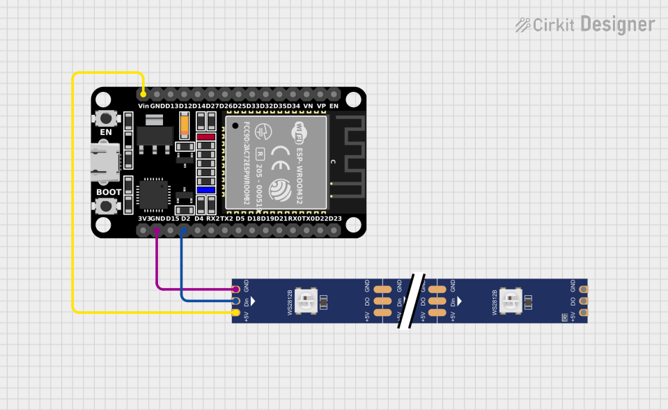
Explore Projects Built with Led Wire Strip
Technical Specifications
- Voltage Rating: Typically 5V, 12V, or 24V DC (check your specific strip for compatibility)
- Current Consumption: Depends on the number of LEDs per meter (e.g., 60 LEDs/m may consume ~0.4A/m at 12V)
- Power Consumption: Varies by density and type of LEDs (e.g., 4.8W/m for standard strips)
- LED Type: SMD (Surface-Mount Device) LEDs, such as 3528, 5050, or 2835
- Color Options: Single-color (e.g., white, red, blue) or RGB (multi-color)
- Cuttable Sections: Typically every 3 LEDs (marked on the strip)
- Adhesive Backing: Pre-applied adhesive for easy mounting
- Waterproofing: Available in IP20 (non-waterproof) or IP65/IP67 (waterproof) variants
Pin Configuration and Descriptions
The pin configuration depends on the type of LED strip (single-color or RGB). Below are the common configurations:
Single-Color LED Strip
| Pin Name | Description |
|---|---|
| + (VCC) | Positive voltage input |
| - (GND) | Ground connection |
RGB LED Strip
| Pin Name | Description |
|---|---|
| + (VCC) | Positive voltage input |
| R | Red channel (connect to PWM) |
| G | Green channel (connect to PWM) |
| B | Blue channel (connect to PWM) |
Usage Instructions
How to Use the Component in a Circuit
- Power Supply: Ensure the power supply matches the voltage rating of the LED strip (e.g., 12V DC for a 12V strip). Use a regulated power supply to avoid damage.
- Connecting the Strip:
- For single-color strips, connect the
+pin to the positive terminal of the power supply and the-pin to the ground. - For RGB strips, connect the
+pin to the positive terminal of the power supply and the R, G, and B pins to a microcontroller or RGB controller.
- For single-color strips, connect the
- Cutting the Strip: Cut the strip only at the marked cut points (usually every 3 LEDs). Cutting elsewhere may damage the circuit.
- Mounting: Peel off the adhesive backing and stick the strip to a clean, dry surface.
Important Considerations and Best Practices
- Current Handling: Ensure the power supply can handle the total current draw of the strip. For example, a 5-meter strip with 60 LEDs/m at 12V may require ~2A.
- Heat Dissipation: For high-power strips, consider using an aluminum channel or heatsink to dissipate heat.
- Polarity: Always check the polarity before connecting the strip to avoid damage.
- Waterproofing: If using the strip outdoors, ensure it is rated for waterproofing (e.g., IP65 or higher).
Example: Connecting an RGB LED Strip to an Arduino UNO
Below is an example of how to control an RGB LED strip using an Arduino UNO and PWM pins.
// Example code to control an RGB LED strip with Arduino UNO
// Ensure the LED strip is connected to the correct pins and powered properly

// Define the PWM pins for the RGB channels
const int redPin = 9;   // Red channel connected to pin 9
const int greenPin = 10; // Green channel connected to pin 10
const int bluePin = 11;  // Blue channel connected to pin 11

void setup() {
  // Set the RGB pins as output
  pinMode(redPin, OUTPUT);
  pinMode(greenPin, OUTPUT);
  pinMode(bluePin, OUTPUT);
}

void loop() {
  // Example: Cycle through colors
  setColor(255, 0, 0); // Red
  delay(1000);         // Wait 1 second
  setColor(0, 255, 0); // Green
  delay(1000);         // Wait 1 second
  setColor(0, 0, 255); // Blue
  delay(1000);         // Wait 1 second
}

// Function to set the RGB color
void setColor(int red, int green, int blue) {
  analogWrite(redPin, red);   // Set red channel brightness
  analogWrite(greenPin, green); // Set green channel brightness
  analogWrite(bluePin, blue);  // Set blue channel brightness
}
Troubleshooting and FAQs
Common Issues Users Might Face
LEDs Not Lighting Up:
- Check the power supply voltage and current rating.
- Verify the connections and ensure correct polarity.
- Inspect the strip for physical damage or broken connections.
Uneven Brightness:
- This may occur due to voltage drop over long strips. Use a power injection point every 2-3 meters.
Flickering LEDs:
- Ensure the power supply is stable and not overloaded.
- Check for loose connections or damaged wires.
RGB Colors Not Displaying Correctly:
- Verify the connections to the R, G, and B pins.
- Ensure the microcontroller or RGB controller is functioning properly.
Solutions and Tips for Troubleshooting
- Use a multimeter to check voltage at various points along the strip.
- If using an Arduino, ensure the PWM pins are correctly configured in the code.
- For waterproof strips, ensure the ends are properly sealed after cutting to maintain waterproofing.
By following this documentation, you can effectively use and troubleshoot LED wire strips in your projects.