How to Use Busbar 60amp - 1 input, 4 output: Examples, Pinouts, and Specs
Introduction
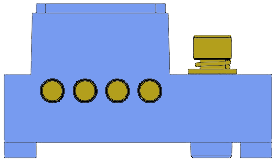
A busbar is a conductive material designed to distribute electrical power efficiently from a single input to multiple outputs. The Busbar 60amp - 1 Input, 4 Output is a compact and robust power distribution component capable of handling up to 60 amps of current. It features one input terminal and four output terminals, making it ideal for applications requiring reliable power distribution to multiple devices or circuits.
Explore Projects Built with Busbar 60amp - 1 input, 4 output


Explore Projects Built with Busbar 60amp - 1 input, 4 output
Common Applications and Use Cases
- Automotive electrical systems (e.g., distributing power to lights, relays, and accessories)
- Marine electrical systems for power distribution
- Solar power systems for connecting multiple loads
- Industrial control panels and machinery
- Battery management systems
Technical Specifications
The following table outlines the key technical details of the Busbar 60amp - 1 Input, 4 Output:
| Parameter | Specification |
|---|---|
| Maximum Current Rating | 60 Amps |
| Voltage Rating | Up to 48V DC |
| Input Terminals | 1 (M8 stud or screw terminal) |
| Output Terminals | 4 (M6 studs or screw terminals) |
| Material | Tin-plated copper (conductive bar) |
| Insulation | High-temperature plastic base |
| Mounting | Screw-mountable base with 2 holes |
| Dimensions | 100mm x 25mm x 20mm (approx.) |
| Operating Temperature | -40°C to +85°C |
Pin Configuration and Descriptions
The Busbar 60amp - 1 Input, 4 Output does not have traditional pins but instead uses screw terminals for connections. Below is a description of the terminals:
| Terminal | Description |
|---|---|
| Input | Single terminal (M8 stud) for connecting the power source (e.g., battery or PSU). |
| Outputs | Four terminals (M6 studs) for connecting loads or circuits. |
| Mounting Holes | Two holes for securely mounting the busbar to a panel or enclosure. |
Usage Instructions
How to Use the Component in a Circuit
- Mount the Busbar: Secure the busbar to a stable surface using the mounting holes and screws. Ensure it is placed in a location with adequate ventilation and away from moisture or conductive surfaces.
- Connect the Input: Attach the power source (e.g., battery positive terminal or power supply output) to the input terminal using an appropriately sized ring terminal and secure it with the M8 nut.
- Connect the Outputs: Attach the devices or circuits to the output terminals using ring terminals and secure them with the M6 nuts. Ensure the total current drawn by all connected devices does not exceed 60 amps.
- Check Connections: Verify all connections are tight and secure to prevent arcing or overheating.
- Power On: Once all connections are verified, power on the system and check for proper operation.
Important Considerations and Best Practices
- Current Rating: Ensure the total current drawn by all connected devices does not exceed the 60-amp rating of the busbar.
- Wire Sizing: Use appropriately sized wires and ring terminals to handle the current without excessive voltage drop or overheating. For 60 amps, use at least 6 AWG wire.
- Insulation: Avoid exposing the busbar to conductive materials that could cause short circuits. Use insulating covers if necessary.
- Environment: Install the busbar in a dry, clean, and vibration-free environment to ensure long-term reliability.
- Torque Specifications: Tighten the nuts on the terminals to the manufacturer-recommended torque to ensure secure connections without damaging the threads.
Example: Connecting to an Arduino UNO
While the busbar itself is not directly connected to an Arduino UNO, it can be used to distribute power to multiple devices in a system that includes an Arduino. For example, you can use the busbar to power sensors, relays, and other peripherals connected to the Arduino.
// Example Arduino code for controlling a relay powered via the busbar

const int relayPin = 7; // Pin connected to the relay control input

void setup() {
  pinMode(relayPin, OUTPUT); // Set the relay pin as an output
  digitalWrite(relayPin, LOW); // Ensure the relay is off at startup
}

void loop() {
  digitalWrite(relayPin, HIGH); // Turn the relay on
  delay(1000); // Keep it on for 1 second
  digitalWrite(relayPin, LOW); // Turn the relay off
  delay(1000); // Keep it off for 1 second
}
Note: Ensure the relay module is powered via the busbar and that the Arduino's control pin is properly isolated using an optocoupler or transistor if necessary.
Troubleshooting and FAQs
Common Issues Users Might Face
Loose Connections: If the connections are not tight, the busbar may overheat or cause intermittent power delivery.
- Solution: Check and tighten all connections. Use a torque wrench if possible to ensure proper tightness.
Overcurrent: Exceeding the 60-amp rating can cause overheating or damage to the busbar.
- Solution: Calculate the total current draw of all connected devices and ensure it is within the 60-amp limit.
Short Circuits: Exposed terminals may come into contact with conductive materials, causing a short circuit.
- Solution: Use insulating covers or place the busbar in an enclosure to prevent accidental contact.
Corrosion: In humid or marine environments, the terminals may corrode over time.
- Solution: Use corrosion-resistant terminals and apply dielectric grease to the connections.
FAQs
Q: Can I use this busbar for AC power distribution?
A: While the busbar is primarily designed for DC applications, it can be used for low-voltage AC power distribution (up to 48V AC). Ensure the current does not exceed 60 amps.
Q: What wire size should I use for the input and outputs?
A: For a 60-amp load, use at least 6 AWG wire. For lower currents, you can use smaller wires, but always follow local electrical codes.
Q: Can I connect more than four devices to the outputs?
A: No, the busbar is designed for four outputs. If you need more connections, consider using additional busbars or terminal blocks.
Q: Is the busbar safe to use in outdoor environments?
A: The busbar should be installed in a weatherproof enclosure if used outdoors to protect it from moisture and corrosion.