Cirkit Designer Logo
Cirkit Designer
Your all-in-one circuit design IDE
Home / 
Component Documentation

How to Use 8192 CPR Enconder AMT102 8192: Examples, Pinouts, and Specs

Image of 8192 CPR Enconder AMT102 8192
Cirkit Designer LogoDesign with 8192 CPR Enconder AMT102 8192 in Cirkit Designer

Introduction

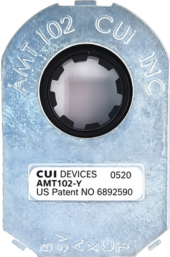
The AMT102 is a high-resolution rotary encoder manufactured by AMT, offering 8192 counts per revolution (CPR). This encoder is designed to provide precise position feedback, making it ideal for applications requiring high accuracy and reliability. Its compact design and robust construction ensure dependable performance, even in demanding industrial environments.

Explore Projects Built with 8192 CPR Enconder AMT102 8192

Use Cirkit Designer to design, explore, and prototype these projects online. Some projects support real-time simulation. Click "Open Project" to start designing instantly!
Configurable Battery-Powered RF Signal Transmitter with DIP Switch Settings
Image of fyp transmitter: A project utilizing 8192 CPR Enconder AMT102 8192 in a practical application
This circuit appears to be a configurable encoder system with an RF transmission capability. The encoder's address pins (A0-A7) are connected to a DIP switch for setting the address, and its data output (DO) is connected to an RF transmitter, allowing the encoded signal to be wirelessly transmitted. The circuit is powered by a 9V battery, regulated to 5V by a 7805 voltage regulator, and includes a diode for polarity protection. Tactile switches are connected to the encoder's data inputs (D1-D3), and an LED with a current-limiting resistor indicates power or activity.
Cirkit Designer LogoOpen Project in Cirkit Designer
Sound and Motion-Activated Switching Circuit with 4017 Decade Counter and BC547 Transistors
Image of m.s: A project utilizing 8192 CPR Enconder AMT102 8192 in a practical application
This circuit is a sequential control system with a 4017 decade counter at its core, driving relays through transistors based on its output states. It includes toggle switches and a PIR sensor for triggering events, a condenser microphone for sound detection, and an LED for visual indication. The circuit operates without a microcontroller, relying on the counter's sequence and external inputs to control the connected loads.
Cirkit Designer LogoOpen Project in Cirkit Designer
Satellite-Based Timing and Navigation System with SDR and Atomic Clock Synchronization
Image of GPS 시스템 측정 구성도_Confirm: A project utilizing 8192 CPR Enconder AMT102 8192 in a practical application
This circuit appears to be a complex system involving power supply management, GPS and timing synchronization, and data communication. It includes a SI-TEX G1 Satellite Compass for GPS data, an XHTF1021 Atomic Rubidium Clock for precise timing, and Ettus USRP B200 units for software-defined radio communication. Power is supplied through various SMPS units and distributed via terminal blocks and DC jacks. Data communication is facilitated by Beelink MINI S12 N95 computers, RS232 splitters, and a 1000BASE-T Media Converter for network connectivity. RF Directional Couplers are used to interface antennas with the USRP units, and the entire system is likely contained within cases for protection and organization.
Cirkit Designer LogoOpen Project in Cirkit Designer
Rotary Encoder Interface with STG Adapter for Signal Processing
Image of Encoder in STG: A project utilizing 8192 CPR Enconder AMT102 8192 in a practical application
The circuit consists of two rotary encoders (Kalamoyi P3022-V1-CW360) connected to two STG adapters. Each encoder's VCC, OUT, and GND pins are connected to the corresponding STG adapter, facilitating signal transmission and power supply management.
Cirkit Designer LogoOpen Project in Cirkit Designer

Explore Projects Built with 8192 CPR Enconder AMT102 8192

Use Cirkit Designer to design, explore, and prototype these projects online. Some projects support real-time simulation. Click "Open Project" to start designing instantly!
Image of fyp transmitter: A project utilizing 8192 CPR Enconder AMT102 8192 in a practical application
Configurable Battery-Powered RF Signal Transmitter with DIP Switch Settings
This circuit appears to be a configurable encoder system with an RF transmission capability. The encoder's address pins (A0-A7) are connected to a DIP switch for setting the address, and its data output (DO) is connected to an RF transmitter, allowing the encoded signal to be wirelessly transmitted. The circuit is powered by a 9V battery, regulated to 5V by a 7805 voltage regulator, and includes a diode for polarity protection. Tactile switches are connected to the encoder's data inputs (D1-D3), and an LED with a current-limiting resistor indicates power or activity.
Cirkit Designer LogoOpen Project in Cirkit Designer
Image of m.s: A project utilizing 8192 CPR Enconder AMT102 8192 in a practical application
Sound and Motion-Activated Switching Circuit with 4017 Decade Counter and BC547 Transistors
This circuit is a sequential control system with a 4017 decade counter at its core, driving relays through transistors based on its output states. It includes toggle switches and a PIR sensor for triggering events, a condenser microphone for sound detection, and an LED for visual indication. The circuit operates without a microcontroller, relying on the counter's sequence and external inputs to control the connected loads.
Cirkit Designer LogoOpen Project in Cirkit Designer
Image of GPS 시스템 측정 구성도_Confirm: A project utilizing 8192 CPR Enconder AMT102 8192 in a practical application
Satellite-Based Timing and Navigation System with SDR and Atomic Clock Synchronization
This circuit appears to be a complex system involving power supply management, GPS and timing synchronization, and data communication. It includes a SI-TEX G1 Satellite Compass for GPS data, an XHTF1021 Atomic Rubidium Clock for precise timing, and Ettus USRP B200 units for software-defined radio communication. Power is supplied through various SMPS units and distributed via terminal blocks and DC jacks. Data communication is facilitated by Beelink MINI S12 N95 computers, RS232 splitters, and a 1000BASE-T Media Converter for network connectivity. RF Directional Couplers are used to interface antennas with the USRP units, and the entire system is likely contained within cases for protection and organization.
Cirkit Designer LogoOpen Project in Cirkit Designer
Image of Encoder in STG: A project utilizing 8192 CPR Enconder AMT102 8192 in a practical application
Rotary Encoder Interface with STG Adapter for Signal Processing
The circuit consists of two rotary encoders (Kalamoyi P3022-V1-CW360) connected to two STG adapters. Each encoder's VCC, OUT, and GND pins are connected to the corresponding STG adapter, facilitating signal transmission and power supply management.
Cirkit Designer LogoOpen Project in Cirkit Designer

Common Applications

  • Robotics: Precise motor control and position feedback
  • CNC Machines: Accurate axis positioning
  • Industrial Automation: Monitoring and controlling rotary motion
  • 3D Printers: Ensuring precise movement of print heads
  • Servo Motors: High-resolution feedback for closed-loop systems

Technical Specifications

Key Technical Details

Parameter Value
Manufacturer AMT
Model AMT102
Resolution 8192 CPR
Supply Voltage 4.5V to 5.5V
Current Consumption 10 mA (typical)
Output Signal Type Quadrature (A, B)
Operating Temperature -40°C to +125°C
Mounting Options Modular, adjustable mounting
Shaft Diameter Support 2mm to 8mm (with adapters)

Pin Configuration and Descriptions

The AMT102 encoder typically uses a 6-pin connector for interfacing. Below is the pinout:

Pin Number Name Description
1 VCC Power supply input (4.5V to 5.5V)
2 GND Ground connection
3 A Quadrature output channel A
4 B Quadrature output channel B
5 Z Index pulse output (1 pulse per revolution)
6 NC Not connected (reserved for future use)

Usage Instructions

How to Use the AMT102 in a Circuit

  1. Power Supply: Connect the VCC pin to a regulated 5V power source and the GND pin to the ground of your circuit.
  2. Signal Connections:
    • Connect the A and B pins to the input pins of your microcontroller or motor driver to read the quadrature signals.
    • Optionally, connect the Z pin if you need an index pulse for absolute positioning.
  3. Mounting: Secure the encoder to the motor shaft using the provided mounting kit. Ensure proper alignment to avoid signal errors.
  4. Signal Reading: Use a microcontroller or dedicated encoder interface to decode the quadrature signals and determine the position or speed.

Important Considerations and Best Practices

  • Debouncing: Use software or hardware debouncing to filter out noise in the quadrature signals.
  • Alignment: Ensure the encoder is properly aligned with the motor shaft to prevent mechanical stress and signal distortion.
  • Shielding: Use shielded cables for signal lines to minimize electromagnetic interference (EMI).
  • Index Pulse: If using the Z pin, ensure your system can handle the single pulse per revolution for absolute positioning.

Example: Connecting to an Arduino UNO

Below is an example of how to connect and read the AMT102 encoder using an Arduino UNO:

Circuit Connections

Encoder Pin Arduino Pin
VCC 5V
GND GND
A Pin 2
B Pin 3

Arduino Code

// Example code to read the AMT102 encoder with Arduino UNO
// Connect encoder A and B outputs to Arduino pins 2 and 3 (interrupt pins)

volatile int position = 0; // Variable to store encoder position

void setup() {
  pinMode(2, INPUT); // Set pin 2 as input for channel A
  pinMode(3, INPUT); // Set pin 3 as input for channel B

  // Attach interrupts to handle encoder signals
  attachInterrupt(digitalPinToInterrupt(2), readEncoder, CHANGE);
  attachInterrupt(digitalPinToInterrupt(3), readEncoder, CHANGE);

  Serial.begin(9600); // Initialize serial communication
}

void loop() {
  // Print the current position to the Serial Monitor
  Serial.print("Position: ");
  Serial.println(position);
  delay(100); // Delay for readability
}

void readEncoder() {
  // Read the current state of channel A and B
  int stateA = digitalRead(2);
  int stateB = digitalRead(3);

  // Determine direction based on quadrature signal
  if (stateA == stateB) {
    position++; // Clockwise rotation
  } else {
    position--; // Counterclockwise rotation
  }
}

Troubleshooting and FAQs

Common Issues and Solutions

  1. No Output Signals

    • Cause: Incorrect wiring or power supply issues.
    • Solution: Verify all connections and ensure the encoder is receiving 5V power.
  2. Inconsistent Position Readings

    • Cause: Mechanical misalignment or noise in the signal.
    • Solution: Check the encoder mounting and use shielded cables to reduce noise.
  3. Index Pulse Not Detected

    • Cause: Z pin not connected or improperly configured.
    • Solution: Ensure the Z pin is connected to the correct input and verify your system's handling of the index pulse.
  4. High Current Consumption

    • Cause: Short circuit or damaged encoder.
    • Solution: Inspect the wiring for shorts and replace the encoder if necessary.

FAQs

Q: Can the AMT102 be used with a 3.3V system?
A: No, the AMT102 requires a supply voltage of 4.5V to 5.5V. Use a level shifter if interfacing with a 3.3V system.

Q: How do I calculate the rotational speed using the encoder?
A: Measure the time between pulses on channel A or B and calculate the speed using the formula:
Speed (RPM) = (Pulses per second / CPR) * 60.

Q: Is the encoder resistant to dust and moisture?
A: The AMT102 is designed for industrial environments but is not fully sealed. Use additional protection in harsh conditions.