How to Use 4-12VDC to 3.3VDC DC-DC Step Down: Examples, Pinouts, and Specs
Introduction
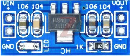
The AMS1117 by MakerBotics is a compact and efficient DC-DC step-down voltage regulator designed to convert an input voltage range of 4-12VDC to a stable output of 3.3VDC. This component is widely used in electronics projects to power low-voltage devices such as microcontrollers, sensors, and communication modules. Its simplicity and reliability make it a popular choice for hobbyists and professionals alike.
Explore Projects Built with 4-12VDC to 3.3VDC DC-DC Step Down


Explore Projects Built with 4-12VDC to 3.3VDC DC-DC Step Down
Common Applications
- Powering microcontrollers (e.g., Arduino, ESP8266, ESP32, Raspberry Pi peripherals)
- Supplying stable 3.3V to sensors and modules (e.g., GPS, Bluetooth, Wi-Fi)
- Battery-powered devices requiring voltage regulation
- General-purpose voltage regulation in embedded systems
Technical Specifications
The AMS1117 is designed to provide a stable 3.3V output with minimal external components. Below are its key technical details:
Key Specifications
| Parameter | Value |
|---|---|
| Input Voltage Range | 4V to 12V |
| Output Voltage | 3.3V ± 1% |
| Maximum Output Current | 800mA |
| Dropout Voltage | 1.1V (typical at 800mA load) |
| Quiescent Current | 5mA (typical) |
| Operating Temperature | -40°C to +125°C |
| Package Type | SOT-223 or TO-252 |
Pin Configuration
The AMS1117 has three pins, as described in the table below:
| Pin Number | Pin Name | Description |
|---|---|---|
| 1 | VIN | Input voltage (4-12VDC) |
| 2 | GND | Ground (0V reference) |
| 3 | VOUT | Regulated output voltage (3.3VDC) |
Typical Circuit Diagram
Below is a simplified circuit diagram for using the AMS1117:
   VIN (4-12V) ----[ AMS1117 ]---- VOUT (3.3V)
                  |          |
                 GND        GND
Note: It is recommended to use input and output capacitors for stability:
- Input capacitor: 10µF (electrolytic or ceramic)
- Output capacitor: 10µF (ceramic)
Usage Instructions
How to Use the AMS1117 in a Circuit
Connect the Input Voltage (VIN):
- Provide a DC voltage between 4V and 12V to the VIN pin.
- Ensure the input voltage is at least 1.1V higher than the desired output (dropout voltage).
Connect the Ground (GND):
- Connect the GND pin to the ground of your circuit.
Connect the Output Voltage (VOUT):
- The VOUT pin provides a stable 3.3V output. Connect this to the load or device requiring 3.3V.
Add Capacitors:
- Place a 10µF capacitor between VIN and GND for input stability.
- Place a 10µF capacitor between VOUT and GND for output stability.
Important Considerations
- Heat Dissipation: The AMS1117 can heat up under high current loads. Use a heatsink or ensure proper ventilation if the current exceeds 500mA.
- Input Voltage Range: Do not exceed 12V on the input, as this may damage the regulator.
- Load Current: Ensure the load does not draw more than 800mA to avoid overheating or instability.
- Bypass Capacitors: Always use the recommended capacitors to prevent oscillations and ensure stable operation.
Example: Using AMS1117 with Arduino UNO
The AMS1117 can be used to power an Arduino UNO or other 3.3V devices. Below is an example of connecting the AMS1117 to an Arduino UNO:
Circuit Connections
- Connect a 9V battery to the VIN pin of the AMS1117.
- Connect the GND pin of the AMS1117 to the Arduino's GND.
- Connect the VOUT pin of the AMS1117 to the 3.3V pin of the Arduino.
Sample Arduino Code
If you are powering a 3.3V sensor (e.g., DHT11) using the AMS1117, you can use the following code:
// Example code for reading data from a DHT11 sensor powered by AMS1117
#include <DHT.h>

#define DHTPIN 2       // Pin connected to the DHT11 data pin
#define DHTTYPE DHT11  // Define the type of DHT sensor

DHT dht(DHTPIN, DHTTYPE);

void setup() {
  Serial.begin(9600);  // Initialize serial communication
  dht.begin();         // Initialize the DHT sensor
  Serial.println("DHT11 Sensor Test");
}

void loop() {
  delay(2000);  // Wait 2 seconds between readings

  float humidity = dht.readHumidity();    // Read humidity
  float temperature = dht.readTemperature();  // Read temperature in Celsius

  // Check if readings are valid
  if (isnan(humidity) || isnan(temperature)) {
    Serial.println("Failed to read from DHT sensor!");
    return;
  }

  // Print the results to the Serial Monitor
  Serial.print("Humidity: ");
  Serial.print(humidity);
  Serial.print(" %\t");
  Serial.print("Temperature: ");
  Serial.print(temperature);
  Serial.println(" °C");
}
Note: Ensure the DHT11 sensor is connected to the 3.3V output of the AMS1117.
Troubleshooting and FAQs
Common Issues
No Output Voltage:
- Check if the input voltage is within the 4-12V range.
- Verify all connections, especially VIN and GND.
- Ensure the load does not exceed 800mA.
Overheating:
- Verify that the input voltage is not too high.
- Check if the load current is within the specified limit.
- Use a heatsink or improve ventilation.
Unstable Output Voltage:
- Ensure the input and output capacitors are properly connected.
- Check for loose or poor connections.
Device Not Powering On:
- Confirm that the output voltage is 3.3V using a multimeter.
- Verify that the load device is compatible with 3.3V.
FAQs
Q: Can I use the AMS1117 to power a 5V device?
A: No, the AMS1117 in this configuration outputs a fixed 3.3V. For 5V output, use a different regulator or version of the AMS1117.
Q: What happens if I exceed the input voltage limit?
A: Exceeding 12V on the input can damage the AMS1117 and potentially cause it to fail permanently.
Q: Can I use the AMS1117 without capacitors?
A: While it may work in some cases, it is highly recommended to use the input and output capacitors to ensure stability and prevent oscillations.
Q: Is the AMS1117 suitable for battery-powered applications?
A: Yes, as long as the battery voltage is within the 4-12V range and the load current does not exceed 800mA.
By following this documentation, you can effectively integrate the AMS1117 into your projects for reliable 3.3V power regulation.