Cirkit Designer Logo
Cirkit Designer
Your all-in-one circuit design IDE
Home / 
Component Documentation

How to Use 5V PSU: Examples, Pinouts, and Specs

Image of 5V PSU
Cirkit Designer LogoDesign with 5V PSU in Cirkit Designer

Introduction

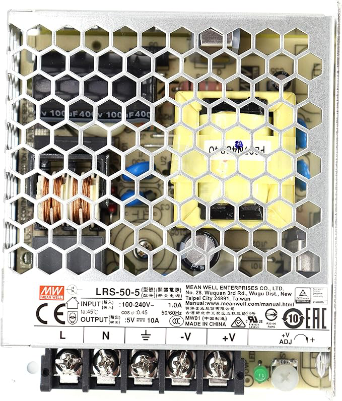
A 5V Power Supply Unit (PSU) provides a stable 5-volt output to power electronic circuits and devices, ensuring consistent voltage for reliable operation. It is a fundamental component in electronics, commonly used to power microcontrollers, sensors, LEDs, and other low-voltage devices. The 5V PSU is essential for projects requiring a reliable and regulated power source.

Explore Projects Built with 5V PSU

Use Cirkit Designer to design, explore, and prototype these projects online. Some projects support real-time simulation. Click "Open Project" to start designing instantly!
12V to 5V Power Supply with LED Indicator and Push Switch
Image of Power Supply LVCO: A project utilizing 5V PSU in a practical application
This circuit is a 12V to 5V regulated power supply with an LED indicator. It uses a 5408 diode for reverse polarity protection, an LM340T5 7805 voltage regulator to step down the voltage to 5V, and a push switch to control the LED indicator. The circuit also includes capacitors for filtering and a resistor to limit the current through the LED.
Cirkit Designer LogoOpen Project in Cirkit Designer
Battery-Powered USB Charger with LED Indicator and DC Motor
Image of Copy of Hand Crank mobile charger : A project utilizing 5V PSU in a practical application
This circuit converts AC power to DC using a bridge rectifier and regulates the voltage to 5V with a 7805 voltage regulator. It powers a USB port and indicates power status with an LED, while also providing a charging interface through a multi-charging cable.
Cirkit Designer LogoOpen Project in Cirkit Designer
Dual 5V Power Supply Distribution Circuit with Toggle Switch Control
Image of rfdriver: A project utilizing 5V PSU in a practical application
This circuit consists of two 5V 5A power supplies connected to an AC wall plug point, providing DC output through a 12-way connector. The ground connections from both power supplies are interconnected and also connected to the ground pins of two toggle switches. The DC outputs from the power supplies are separately connected to different pins on the 12-way connector, with each power supply output being switchable via one of the toggle switches.
Cirkit Designer LogoOpen Project in Cirkit Designer
USB-Powered DC Gear Motor with LED Indicator
Image of Hand Crank mobile charger : A project utilizing 5V PSU in a practical application
This circuit appears to be a power supply unit with a bridge rectifier connected to a DC gear motor, indicating it is designed to convert AC to DC power for the motor. An electrolytic capacitor is used for smoothing the DC output, and a 7805 voltage regulator is included to provide a stable 5V output. Additionally, there is an LED with a series resistor, likely serving as a power indicator light.
Cirkit Designer LogoOpen Project in Cirkit Designer

Explore Projects Built with 5V PSU

Use Cirkit Designer to design, explore, and prototype these projects online. Some projects support real-time simulation. Click "Open Project" to start designing instantly!
Image of Power Supply LVCO: A project utilizing 5V PSU in a practical application
12V to 5V Power Supply with LED Indicator and Push Switch
This circuit is a 12V to 5V regulated power supply with an LED indicator. It uses a 5408 diode for reverse polarity protection, an LM340T5 7805 voltage regulator to step down the voltage to 5V, and a push switch to control the LED indicator. The circuit also includes capacitors for filtering and a resistor to limit the current through the LED.
Cirkit Designer LogoOpen Project in Cirkit Designer
Image of Copy of Hand Crank mobile charger : A project utilizing 5V PSU in a practical application
Battery-Powered USB Charger with LED Indicator and DC Motor
This circuit converts AC power to DC using a bridge rectifier and regulates the voltage to 5V with a 7805 voltage regulator. It powers a USB port and indicates power status with an LED, while also providing a charging interface through a multi-charging cable.
Cirkit Designer LogoOpen Project in Cirkit Designer
Image of rfdriver: A project utilizing 5V PSU in a practical application
Dual 5V Power Supply Distribution Circuit with Toggle Switch Control
This circuit consists of two 5V 5A power supplies connected to an AC wall plug point, providing DC output through a 12-way connector. The ground connections from both power supplies are interconnected and also connected to the ground pins of two toggle switches. The DC outputs from the power supplies are separately connected to different pins on the 12-way connector, with each power supply output being switchable via one of the toggle switches.
Cirkit Designer LogoOpen Project in Cirkit Designer
Image of Hand Crank mobile charger : A project utilizing 5V PSU in a practical application
USB-Powered DC Gear Motor with LED Indicator
This circuit appears to be a power supply unit with a bridge rectifier connected to a DC gear motor, indicating it is designed to convert AC to DC power for the motor. An electrolytic capacitor is used for smoothing the DC output, and a 7805 voltage regulator is included to provide a stable 5V output. Additionally, there is an LED with a series resistor, likely serving as a power indicator light.
Cirkit Designer LogoOpen Project in Cirkit Designer

Common Applications and Use Cases

  • Powering microcontrollers like Arduino, Raspberry Pi, and ESP32.
  • Supplying power to sensors, modules, and small motors.
  • Driving LED strips and displays.
  • Providing a stable voltage source for breadboard prototyping.
  • Charging USB-powered devices.

Technical Specifications

Below are the key technical details of a typical 5V PSU:

Parameter Specification
Input Voltage Range 100-240V AC (for AC-DC PSUs)
Output Voltage 5V DC
Output Current 500mA to 3A (varies by model)
Ripple and Noise <50mV
Efficiency ≥80%
Protection Features Overcurrent, Overvoltage, Short Circuit
Operating Temperature -10°C to 50°C

Pin Configuration and Descriptions

For a typical 5V PSU with a DC barrel jack or screw terminals:

Pin/Terminal Description
Positive (+) Provides the regulated 5V DC output.
Negative (-) Ground connection (0V reference).

For USB-powered 5V PSUs:

Pin Description
VBUS Provides the regulated 5V DC output.
GND Ground connection (0V reference).

Usage Instructions

How to Use the 5V PSU in a Circuit

  1. Connect the Input Power Source:
    • For AC-DC PSUs, plug the unit into a standard AC outlet.
    • For USB-powered PSUs, connect the USB cable to a power source (e.g., a computer or USB adapter).
  2. Connect the Output Terminals:
    • Identify the positive (+) and negative (-) terminals.
    • Connect the positive terminal to the VCC or power input of your circuit.
    • Connect the negative terminal to the GND of your circuit.
  3. Verify Connections:
    • Double-check all connections to ensure proper polarity.
    • Use a multimeter to confirm the output voltage is 5V before powering sensitive components.
  4. Power On:
    • Turn on the PSU or connect it to the power source.
    • Monitor the circuit for proper operation.

Important Considerations and Best Practices

  • Avoid Overloading: Ensure the total current draw of your circuit does not exceed the PSU's maximum current rating.
  • Heat Management: If the PSU becomes excessively hot, reduce the load or improve ventilation.
  • Polarity Protection: Use a diode in series with the positive terminal to prevent damage from reverse polarity.
  • Decoupling Capacitors: Add capacitors (e.g., 100µF and 0.1µF) near the power input of your circuit to filter noise and stabilize the voltage.

Example: Using a 5V PSU with an Arduino UNO

The 5V PSU can be used to power an Arduino UNO via its 5V pin. Below is an example of how to connect and use it:

  1. Connect the positive terminal of the PSU to the 5V pin on the Arduino.
  2. Connect the negative terminal of the PSU to the GND pin on the Arduino.
  3. Upload the following code to the Arduino to blink an LED:
// This code blinks an LED connected to pin 13 of the Arduino UNO.
// Ensure the 5V PSU is properly connected to the Arduino's 5V and GND pins.

void setup() {
  pinMode(13, OUTPUT); // Set pin 13 as an output pin
}

void loop() {
  digitalWrite(13, HIGH); // Turn the LED on
  delay(1000);            // Wait for 1 second
  digitalWrite(13, LOW);  // Turn the LED off
  delay(1000);            // Wait for 1 second
}

Troubleshooting and FAQs

Common Issues and Solutions

  1. No Output Voltage:

    • Cause: The PSU is not receiving input power.
    • Solution: Check the input power source and connections. Ensure the PSU is turned on.
  2. Voltage Drops Under Load:

    • Cause: The connected load exceeds the PSU's current rating.
    • Solution: Reduce the load or use a PSU with a higher current rating.
  3. Overheating:

    • Cause: The PSU is operating near or beyond its maximum power rating.
    • Solution: Improve ventilation or reduce the load.
  4. Noise or Ripple in Output Voltage:

    • Cause: Insufficient filtering or high-frequency interference.
    • Solution: Add decoupling capacitors near the load.

FAQs

Q: Can I use a 5V PSU to charge a smartphone?
A: Yes, if the PSU has a USB output and the current rating matches the smartphone's charging requirements.

Q: What happens if I reverse the polarity of the connections?
A: Reversing polarity can damage your circuit. Use a diode or double-check connections to prevent this.

Q: Can I use a 5V PSU to power a 3.3V device?
A: No, a 5V PSU will damage 3.3V devices. Use a voltage regulator or step-down converter to reduce the voltage.

Q: How do I know if my PSU is overloaded?
A: Symptoms of overloading include voltage drops, overheating, or the PSU shutting down. Reduce the load to resolve this.