How to Use Arduino Mega 2560 Pro Mini: Examples, Pinouts, and Specs
Introduction
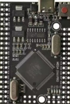
The Arduino Mega 2560 Pro Mini is a compact and powerful microcontroller board based on the ATmega2560. It offers the same functionality as the standard Arduino Mega 2560 but in a smaller form factor, making it ideal for projects where space is limited. This board is widely used in robotics, IoT applications, and complex projects requiring multiple I/O pins and high processing power.
Explore Projects Built with Arduino Mega 2560 Pro Mini
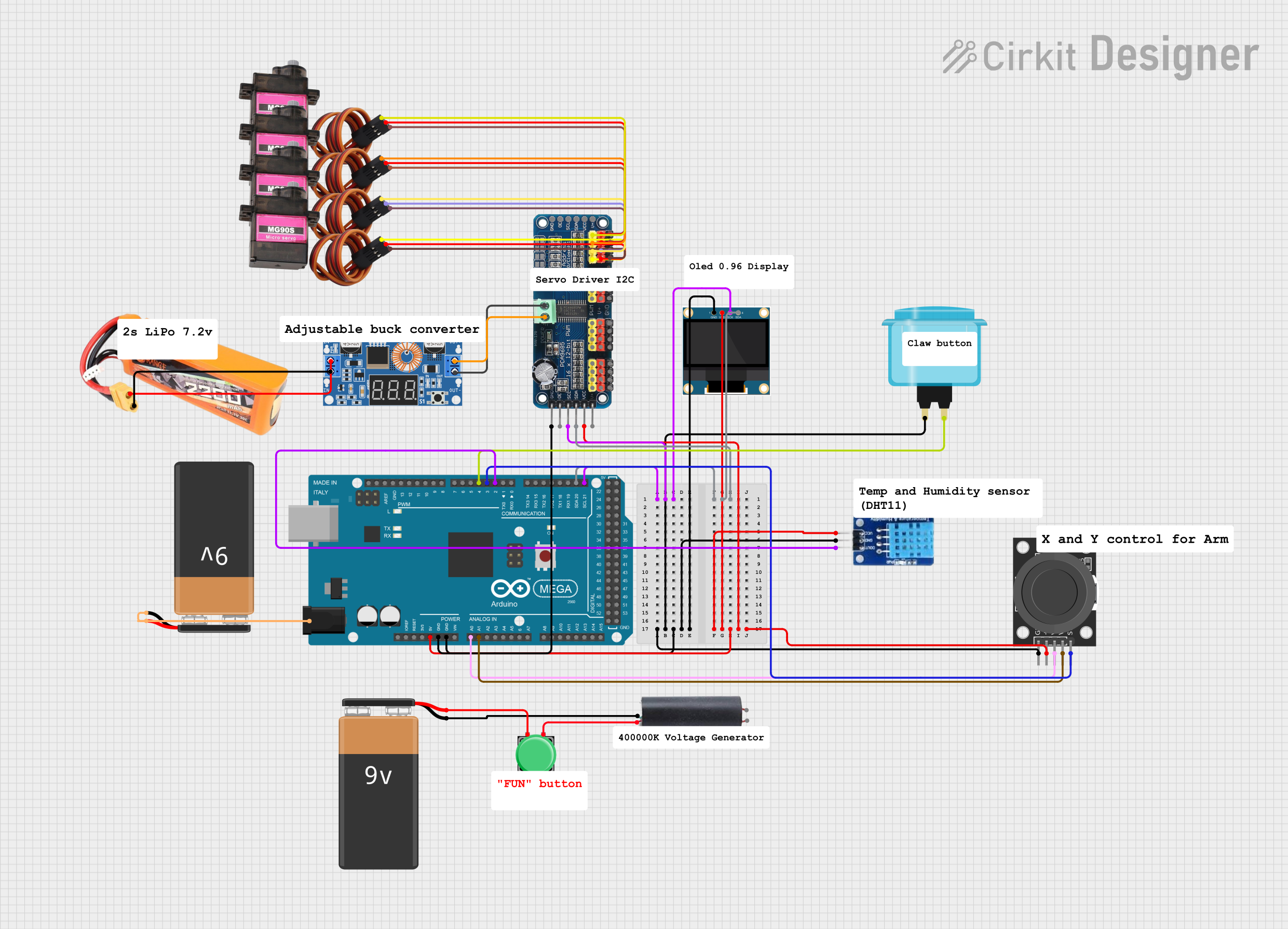
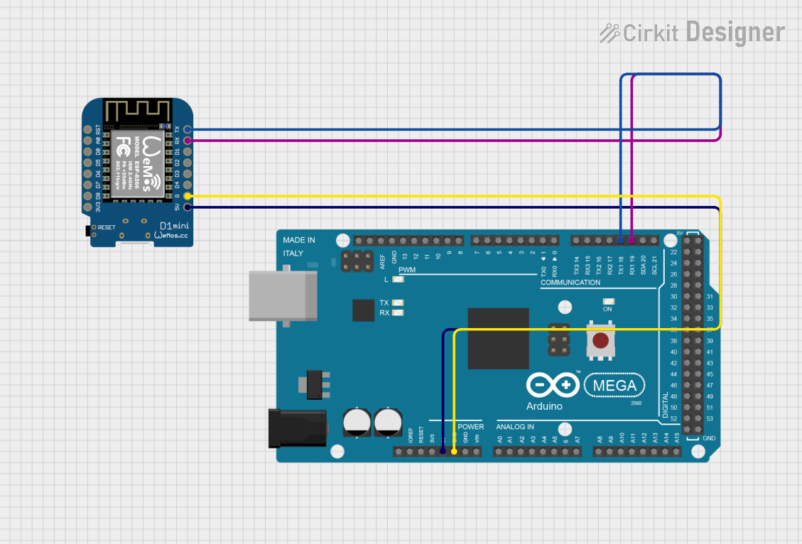
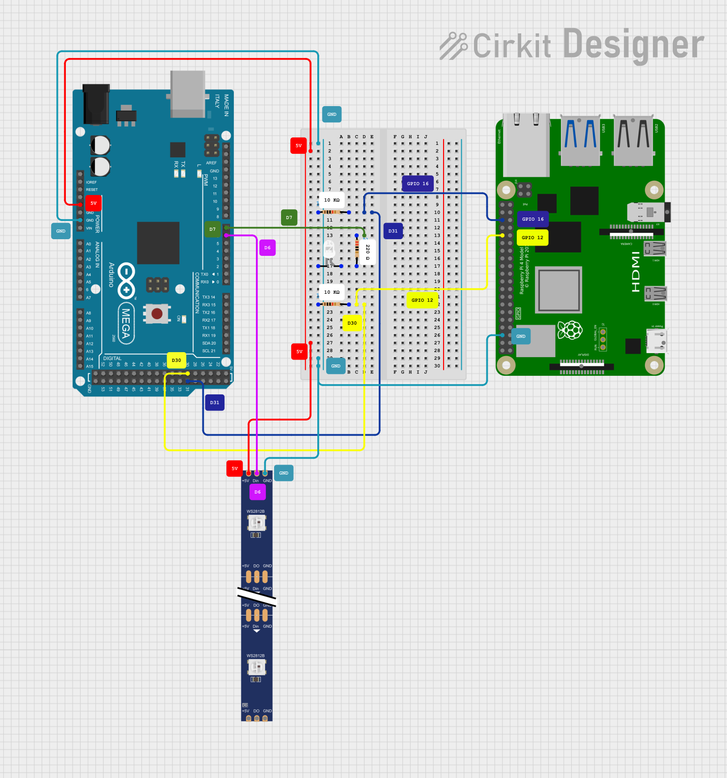
Explore Projects Built with Arduino Mega 2560 Pro Mini
Common Applications and Use Cases
- Robotics and automation systems
- IoT devices and smart home projects
- Data logging and sensor networks
- Prototyping for advanced electronics projects
- Projects requiring multiple serial communication interfaces
Technical Specifications
The Arduino Mega 2560 Pro Mini is designed to provide high performance in a compact size. Below are its key technical details:
Key Technical Details
| Specification | Value |
|---|---|
| Microcontroller | ATmega2560 |
| Operating Voltage | 5V |
| Input Voltage (recommended) | 7-12V |
| Input Voltage (limit) | 6-20V |
| Digital I/O Pins | 54 (15 PWM outputs) |
| Analog Input Pins | 16 |
| Flash Memory | 256 KB (8 KB used by bootloader) |
| SRAM | 8 KB |
| EEPROM | 4 KB |
| Clock Speed | 16 MHz |
| Dimensions | 38mm x 55mm |
Pin Configuration and Descriptions
The Arduino Mega 2560 Pro Mini has a rich set of pins for various functionalities. Below is the pin configuration:
Digital Pins
| Pin Number | Functionality |
|---|---|
| 0-1 | Serial Communication (RX/TX) |
| 2-13 | Digital I/O, PWM on 2-13 |
| 14-21 | Additional Digital I/O |
| 22-53 | General Digital I/O |
Analog Pins
| Pin Number | Functionality |
|---|---|
| A0-A15 | Analog Input (10-bit ADC) |
Power Pins
| Pin Name | Description |
|---|---|
| VIN | Input voltage to the board |
| 5V | Regulated 5V output |
| 3.3V | Regulated 3.3V output |
| GND | Ground |
| RESET | Reset the microcontroller |
Usage Instructions
The Arduino Mega 2560 Pro Mini is versatile and easy to use. Below are the steps and best practices for using this board in your projects.
How to Use the Component in a Circuit
Powering the Board:
- Use the VIN pin to supply 7-12V for optimal performance.
- Alternatively, connect a regulated 5V supply to the 5V pin.
- Ensure the power source can provide sufficient current for your project.
Connecting Peripherals:
- Use the digital pins for controlling LEDs, relays, or other digital devices.
- Connect sensors to the analog pins for reading analog signals.
- Use the PWM pins for controlling motors or dimming LEDs.
Programming the Board:
- Connect the board to your computer using a USB-to-serial adapter.
- Select "Arduino Mega 2560" as the board type in the Arduino IDE.
- Upload your code to the board.
Important Considerations and Best Practices
- Avoid exceeding the voltage limits of the board to prevent damage.
- Use decoupling capacitors near sensors and modules to reduce noise.
- When using high-current devices, ensure proper heat dissipation and power management.
- Use level shifters when interfacing with 3.3V devices.
Example Code for Arduino Mega 2560 Pro Mini
Below is an example code to blink an LED connected to pin 13:
// This example code blinks an LED connected to pin 13 on the Arduino Mega 2560 Pro Mini.
// The LED will turn on for 1 second and off for 1 second in a loop.

void setup() {
  pinMode(13, OUTPUT); // Set pin 13 as an output pin
}

void loop() {
  digitalWrite(13, HIGH); // Turn the LED on
  delay(1000);            // Wait for 1 second
  digitalWrite(13, LOW);  // Turn the LED off
  delay(1000);            // Wait for 1 second
}
Troubleshooting and FAQs
Common Issues Users Might Face
Board Not Detected by the Computer:
- Ensure the USB-to-serial adapter is properly connected.
- Install the correct drivers for the adapter.
Code Upload Fails:
- Verify that the correct board and port are selected in the Arduino IDE.
- Check for loose connections or damaged cables.
Power Issues:
- Ensure the input voltage is within the recommended range.
- Check for short circuits or overloaded pins.
Unresponsive Board:
- Press the reset button to restart the microcontroller.
- Re-upload the code to ensure proper functionality.
Solutions and Tips for Troubleshooting
- Use a multimeter to check voltage levels and continuity in your circuit.
- Test the board with a simple sketch (e.g., blinking an LED) to verify its functionality.
- Disconnect all peripherals and test the board standalone to isolate issues.
- Refer to the Arduino Mega 2560 Pro Mini datasheet for detailed technical information.
By following this documentation, you can effectively use the Arduino Mega 2560 Pro Mini in your projects and troubleshoot common issues with ease.