How to Use Adafruit Trinket M0: Examples, Pinouts, and Specs

 Design with Adafruit Trinket M0 in Cirkit Designer
Introduction
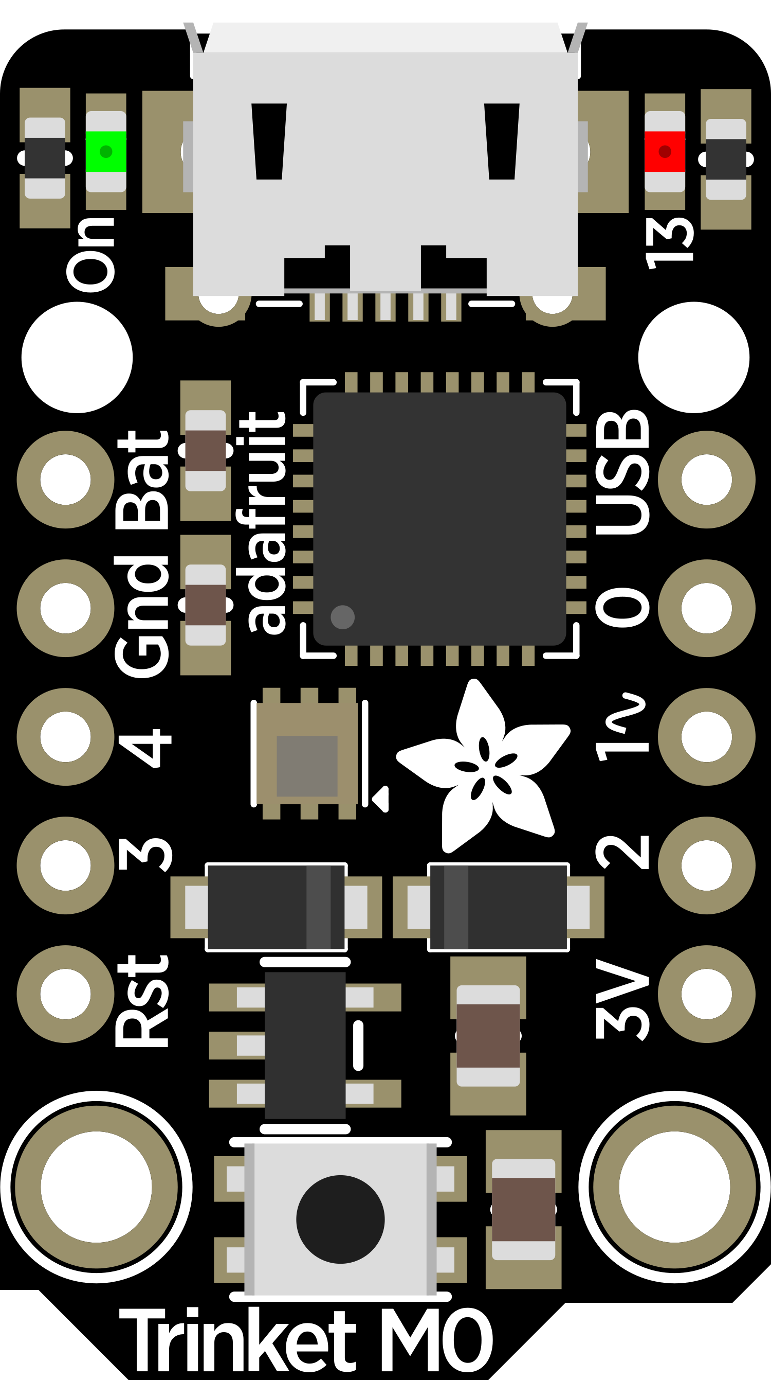
The Adafruit Trinket M0 is a versatile and compact microcontroller board that serves as an excellent tool for hobbyists and professionals alike. Based on the ATSAMD21G18 ARM Cortex M0+ processor, the Trinket M0 is compatible with the Arduino Integrated Development Environment (IDE), which allows for easy programming and prototyping. Its small size makes it ideal for wearable projects, Internet of Things (IoT) applications, and any project where space is at a premium.
Explore Projects Built with Adafruit Trinket M0

 Open Project in Cirkit Designer
 Open Project in Cirkit Designer
 Open Project in Cirkit Designer
 Open Project in Cirkit Designer
Explore Projects Built with Adafruit Trinket M0

 Open Project in Cirkit Designer
 Open Project in Cirkit Designer
 Open Project in Cirkit Designer
 Open Project in Cirkit Designer
Technical Specifications
Key Technical Details
- Microcontroller: ATSAMD21G18, 32-bit ARM Cortex M0+
- Operating Voltage: 3.3V
- Input Voltage: 5V via USB or 3.5-6V via battery input
- Digital I/O Pins: 5
- PWM Channels: 2
- Analog Input Channels: 4
- Flash Memory: 256KB
- SRAM: 32KB
- Clock Speed: 48 MHz
- Dimensions: 27mm x 15.3mm x 2.75mm
Pin Configuration and Descriptions
| Pin Number | Name | Description |
|---|---|---|
| 1 | GND | Ground pin |
| 2 | BAT+ | Battery + input for an external power source |
| 3 | 5V | Regulated 5V output from USB or battery input |
| 4 | USB | Micro-USB connector for programming and power |
| 5 | D0 | Digital I/O, also an analog input (A0) |
| 6 | D1 | Digital I/O, also an analog input (A1), PWM capable |
| 7 | D2 | Digital I/O, also an analog input (A2), PWM capable |
| 8 | D3 | Digital I/O, also an analog input (A3) |
| 9 | D4 | Digital I/O, also used for LED signaling |
| 10 | RST | Reset pin, can be used to restart the microcontroller |
Usage Instructions
Integrating with a Circuit
To use the Adafruit Trinket M0 in a circuit:
- Connect the Trinket M0 to your computer using a micro-USB cable.
- Ensure that the Arduino IDE is installed and configured for the Trinket M0.
- Write or upload your code to the board using the Arduino IDE.
- If using an external power source, connect it to the BAT+ and GND pins.
- Connect other electronic components to the Trinket M0's I/O pins as required by your project.
Important Considerations and Best Practices
- Always ensure that the power supply voltage does not exceed the recommended range.
- When using PWM, remember that not all pins support this feature.
- Use the onboard LED on pin D4 for debugging and status indication.
- Avoid drawing more than 20 mA from any I/O pin.
- Make sure to use pull-up or pull-down resistors with inputs to prevent floating pins.
Example Code for Arduino UNO
Here is a simple example of how to blink the onboard LED using the Arduino IDE:
// Pin D4 has the LED on Trinket M0
int ledPin = 4;

void setup() {
  // Set the digital pin as output
  pinMode(ledPin, OUTPUT);
}

void loop() {
  digitalWrite(ledPin, HIGH);   // Turn the LED on
  delay(1000);                  // Wait for a second
  digitalWrite(ledPin, LOW);    // Turn the LED off
  delay(1000);                  // Wait for a second
}
Troubleshooting and FAQs
Common Issues
- Trinket M0 not recognized by computer: Ensure that the micro-USB cable is properly connected and that it is a data cable capable of transmitting data, not just a charging cable.
- Sketch not uploading: Check that the correct board and port are selected in the Arduino IDE. Press the reset button on the Trinket M0 twice quickly to enter bootloader mode if necessary.
- Unexpected behavior in circuits: Verify that all connections are secure and that components are functioning correctly. Ensure that the power supply is stable and within the specified range.
FAQs
Q: Can I power the Trinket M0 with a battery? A: Yes, you can power the Trinket M0 with an external battery connected to the BAT+ and GND pins.
Q: How do I program the Trinket M0? A: You can program the Trinket M0 using the Arduino IDE. Select the Adafruit Trinket M0 board from the board manager, connect the board via USB, and upload your code.
Q: What is the maximum current that the I/O pins can handle? A: The maximum current per I/O pin should not exceed 20 mA.
For further assistance, refer to the Adafruit Trinket M0 forums and support channels.