How to Use Power Transformer (220V to 12V): Examples, Pinouts, and Specs
Introduction
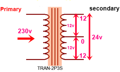
A power transformer is an essential component in many electronic circuits, particularly in power supply systems. This device converts high-voltage 220V AC mains electricity to a lower, safer 12V AC. This step-down process is crucial for providing manageable voltage levels for various electronic devices and systems. Power transformers are commonly used in household appliances, industrial equipment, and electronic projects.
Explore Projects Built with Power Transformer (220V to 12V)


Explore Projects Built with Power Transformer (220V to 12V)
Technical Specifications
Key Technical Details
| Parameter | Value |
|---|---|
| Input Voltage | 220V AC |
| Output Voltage | 12V AC |
| Frequency | 50/60 Hz |
| Power Rating | Varies (e.g., 10W, 20W) |
| Efficiency | Typically 90-95% |
| Insulation Class | Class B or F |
| Temperature Rise | 40-60°C |
Pin Configuration and Descriptions
| Pin Number | Description |
|---|---|
| 1 | Primary winding (220V AC) |
| 2 | Primary winding (220V AC) |
| 3 | Secondary winding (12V AC) |
| 4 | Secondary winding (12V AC) |
Usage Instructions
How to Use the Component in a Circuit
- Safety First: Ensure that the transformer is disconnected from any power source before handling.
- Primary Winding Connection: Connect the primary winding pins (Pin 1 and Pin 2) to the 220V AC mains supply. Use appropriate connectors and ensure secure connections to avoid any electrical hazards.
- Secondary Winding Connection: Connect the secondary winding pins (Pin 3 and Pin 4) to the load or the next stage of your circuit, which requires 12V AC.
- Mounting: Securely mount the transformer to a stable surface using screws or brackets to prevent movement and vibration.
Important Considerations and Best Practices
- Isolation: Ensure proper electrical isolation between the primary and secondary windings to prevent any risk of electric shock.
- Ventilation: Provide adequate ventilation around the transformer to dissipate heat and prevent overheating.
- Fusing: Use appropriate fuses on both the primary and secondary sides to protect against overcurrent conditions.
- Grounding: Properly ground the transformer chassis to enhance safety and reduce electrical noise.
Troubleshooting and FAQs
Common Issues Users Might Face
No Output Voltage:
- Cause: No input power or faulty connections.
- Solution: Check the input power supply and ensure all connections are secure.
Overheating:
- Cause: Overloading or poor ventilation.
- Solution: Reduce the load or improve ventilation around the transformer.
Humming Noise:
- Cause: Loose laminations or mounting.
- Solution: Tighten the mounting screws and ensure the transformer is securely fixed.
Voltage Drop:
- Cause: Excessive load or long cable runs.
- Solution: Reduce the load or use thicker cables to minimize voltage drop.
Solutions and Tips for Troubleshooting
- Check Connections: Always double-check all connections for tightness and correctness.
- Measure Voltages: Use a multimeter to measure input and output voltages to ensure they are within expected ranges.
- Inspect for Damage: Look for any visible signs of damage or wear on the transformer and replace if necessary.
- Consult Datasheets: Refer to the transformer’s datasheet for specific details and recommendations.
Example Code for Arduino UNO
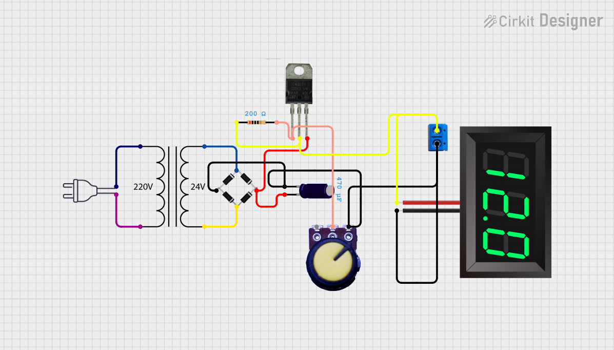
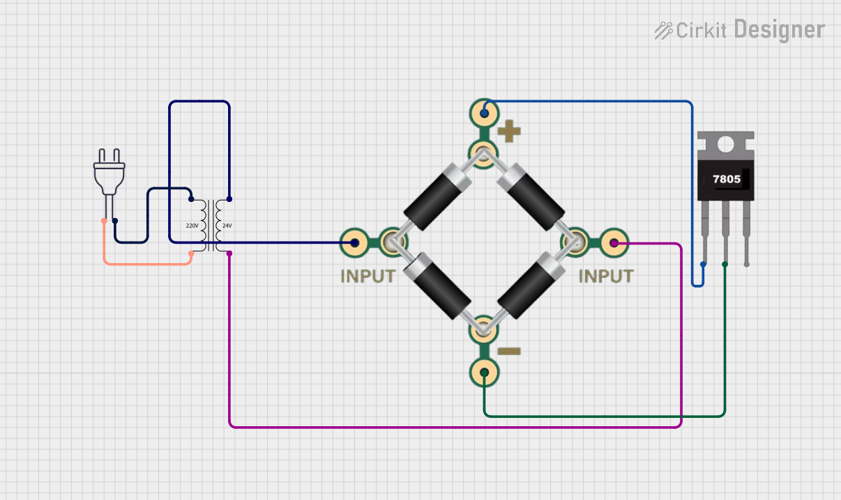
While a power transformer itself is not directly interfaced with an Arduino UNO, it can be part of a power supply circuit that powers the Arduino. Below is an example of how to use a 12V AC to 12V DC rectifier circuit to power an Arduino UNO.
/*
 * Example code to read an analog sensor value
 * and print it to the Serial Monitor.
 * Ensure the Arduino is powered by a 12V DC
 * power supply derived from the transformer.
 */

const int sensorPin = A0; // Analog input pin for the sensor

void setup() {
  Serial.begin(9600); // Initialize serial communication at 9600 baud
}

void loop() {
  int sensorValue = analogRead(sensorPin); // Read the sensor value
  Serial.print("Sensor Value: ");
  Serial.println(sensorValue); // Print the sensor value to the Serial Monitor
  delay(1000); // Wait for 1 second before the next reading
}
This code assumes that the Arduino UNO is powered by a 12V DC power supply derived from the 12V AC output of the transformer, which has been rectified and regulated to 12V DC.
By following this documentation, users can effectively utilize a power transformer in their electronic projects, ensuring safe and efficient operation.