How to Use 5.8 GHz VTX: Examples, Pinouts, and Specs

 Design with 5.8 GHz VTX in Cirkit Designer
Introduction
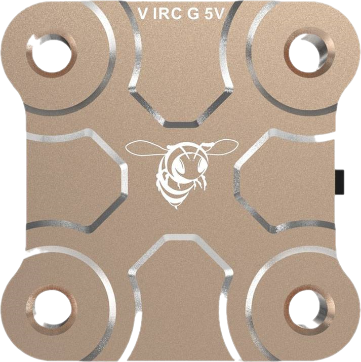
A 5.8 GHz Video Transmitter (VTX) is a critical component in FPV (First Person View) systems, enabling the wireless transmission of video signals from a camera to a receiver. Operating in the 5.8 GHz frequency band, this VTX provides low-latency video transmission, making it ideal for applications such as drone racing, aerial photography, and remote-controlled vehicles. Its compact design and high-frequency operation ensure minimal interference and high-quality video streaming.
Explore Projects Built with 5.8 GHz VTX

 Open Project in Cirkit Designer
 Open Project in Cirkit Designer
 Open Project in Cirkit Designer
 Open Project in Cirkit Designer
Explore Projects Built with 5.8 GHz VTX

 Open Project in Cirkit Designer
 Open Project in Cirkit Designer
 Open Project in Cirkit Designer
 Open Project in Cirkit Designer
Common Applications and Use Cases
- Drone Racing: Real-time video feed for pilots to navigate courses.
- Aerial Photography: Transmitting live video from drones to ground stations.
- RC Vehicles: Providing a first-person view for remote-controlled cars, boats, and planes.
- Surveillance Systems: Wireless video transmission for security and monitoring.
Technical Specifications
The following table outlines the key technical details of a typical 5.8 GHz VTX:
| Parameter | Specification |
|---|---|
| Frequency Band | 5.8 GHz (5.725 GHz - 5.875 GHz) |
| Channels | 40 or more selectable channels |
| Output Power | 25 mW, 200 mW, 500 mW, or 1 W (adjustable) |
| Input Voltage | 7V - 24V (2S to 6S LiPo compatible) |
| Video Input Format | NTSC/PAL |
| Antenna Connector | SMA or RP-SMA |
| Dimensions | Typically 30mm x 20mm x 10mm |
| Weight | ~10-20 grams (varies by model) |
| Operating Temperature | -10°C to 60°C |
Pin Configuration and Descriptions
The pinout for a 5.8 GHz VTX typically includes the following connections:
| Pin | Label | Description |
|---|---|---|
| 1 | VCC | Power input (7V - 24V) |
| 2 | GND | Ground connection |
| 3 | VIDEO IN | Analog video input from the camera |
| 4 | AUDIO IN | Optional audio input (if supported) |
| 5 | SMART AUDIO | UART connection for channel and power configuration |
Usage Instructions
How to Use the 5.8 GHz VTX in a Circuit
- Power Connection: Connect the VCC pin to a power source (7V - 24V) and the GND pin to the ground. Ensure the power source matches the VTX's voltage requirements.
- Video Input: Connect the VIDEO IN pin to the video output of your FPV camera. Ensure the camera is compatible with NTSC or PAL formats.
- Antenna Installation: Attach a compatible 5.8 GHz antenna (SMA or RP-SMA) to the VTX. Always connect the antenna before powering the VTX to avoid damage.
- Channel Selection: Use the onboard buttons or a UART connection (via SMART AUDIO) to select the desired frequency channel and output power.
- Mounting: Secure the VTX to your drone or vehicle using vibration-dampening materials to protect it from mechanical stress.
Important Considerations and Best Practices
- Antenna Safety: Never power the VTX without an antenna connected, as this can damage the transmitter.
- Heat Management: VTXs can generate significant heat during operation. Ensure proper ventilation or use a heatsink to prevent overheating.
- Frequency Selection: Choose a frequency channel that minimizes interference with other devices in the 5.8 GHz band.
- Regulatory Compliance: Check local regulations for allowable transmission power and frequency usage.
Example: Connecting a 5.8 GHz VTX to an Arduino UNO
While the VTX itself does not directly interface with an Arduino, you can use an Arduino to control its settings via the SMART AUDIO protocol. Below is an example of how to send UART commands to configure the VTX:
#include <SoftwareSerial.h>

// Define RX and TX pins for SoftwareSerial
SoftwareSerial vtxSerial(10, 11); // RX = pin 10, TX = pin 11

void setup() {
  // Initialize serial communication with the VTX
  vtxSerial.begin(9600); // Baud rate for SMART AUDIO communication
  Serial.begin(9600);    // For debugging via Serial Monitor

  // Example: Send a command to set the VTX to a specific channel
  setVTXChannel(1); // Set to channel 1 (example)
}

void loop() {
  // Main loop can be used for additional commands or monitoring
}

// Function to send a command to set the VTX channel
void setVTXChannel(uint8_t channel) {
  // SMART AUDIO command to set channel (example format)
  uint8_t command[] = {0xAA, 0x55, 0x01, channel, 0x00};
  // Replace 0x00 with checksum if required by your VTX

  // Send the command to the VTX
  vtxSerial.write(command, sizeof(command));
  Serial.println("Channel set command sent.");
}
Note: The SMART AUDIO protocol may vary between VTX models. Refer to your VTX's datasheet for specific command formats and baud rates.
Troubleshooting and FAQs
Common Issues and Solutions
No Video Signal on Receiver
- Cause: Incorrect channel or frequency mismatch.
- Solution: Ensure the VTX and receiver are set to the same frequency and channel.
Overheating
- Cause: Insufficient airflow or prolonged operation at high power.
- Solution: Add a heatsink or improve ventilation around the VTX.
Poor Video Quality
- Cause: Interference or low transmission power.
- Solution: Increase the output power or switch to a less congested frequency channel.
VTX Not Powering On
- Cause: Incorrect voltage or damaged components.
- Solution: Verify the input voltage and check for loose connections.
FAQs
Q: Can I use the VTX without an antenna?
A: No, powering the VTX without an antenna can damage the transmitter.Q: How far can the VTX transmit video?
A: Transmission range depends on the output power, antenna type, and environmental conditions. Typical ranges are 500m to 2km.Q: Is the VTX compatible with digital video signals?
A: No, most 5.8 GHz VTXs are designed for analog video signals (NTSC/PAL).Q: Can I use the VTX indoors?
A: Yes, but ensure compliance with local regulations regarding transmission power and frequency usage.