Cirkit Designer Logo
Cirkit Designer
Your all-in-one circuit design IDE
Home / 
Component Documentation

How to Use Analog Meter: Examples, Pinouts, and Specs

Image of Analog Meter
Cirkit Designer LogoDesign with Analog Meter in Cirkit Designer

Introduction

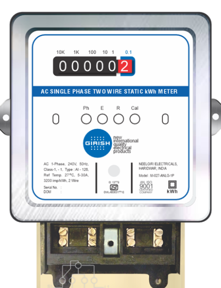
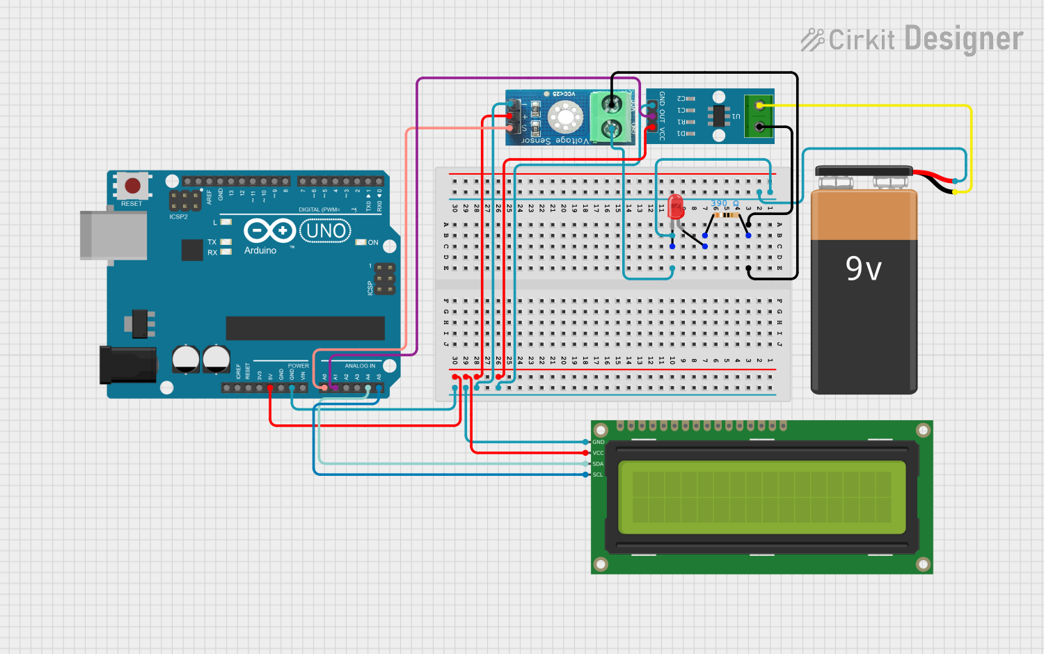
An analog meter, also known as an analog multimeter or a voltmeter, is an essential tool in the field of electronics. Manufactured by Girish, this device is designed to measure various electrical parameters such as current, voltage, and resistance. The meter features a needle that moves over a calibrated scale, providing a visual representation of the measurement. Common applications include troubleshooting electrical circuits, testing batteries, and measuring the output of power supplies.

Explore Projects Built with Analog Meter

Use Cirkit Designer to design, explore, and prototype these projects online. Some projects support real-time simulation. Click "Open Project" to start designing instantly!
ESP32-Based Relay Control System with Visual Indicators
Image of SMART POWER CONTROL SYSTEM: A project utilizing Analog Meter in a practical application
This circuit uses an ESP32 microcontroller to control two KF-301 relays, which in turn switch power to two bulbs. An analog meter is connected in parallel with a red LED, possibly to indicate the status or measure the current. The entire circuit is powered by a 5V DC source.
Cirkit Designer LogoOpen Project in Cirkit Designer
DC Voltage Measurement Circuit with LM393 and Digital Volt/Ammeter
Image of Simple: A project utilizing Analog Meter in a practical application
This circuit consists of a DC power source connected to a mini digital volt/ammeter. The volt/ammeter measures the voltage supplied by the DC power source, with the ground and positive terminals of the power source connected to the corresponding ground and voltage reading pins of the volt/ammeter.
Cirkit Designer LogoOpen Project in Cirkit Designer
Arduino UNO and Adafruit ADS1015 Based Analog to Digital Conversion
Image of relan: A project utilizing Analog Meter in a practical application
This circuit is designed to measure analog voltage levels using a potentiometer and convert them to digital values with an Adafruit ADS1015 12Bit I2C ADC. The Arduino UNO serves as the controller, reading the ADC values via I2C communication and outputting the results to the serial monitor. A 9V battery powers the circuit, and a resistor is used to connect the potentiometer's output to the ADC's analog input channel AIN0.
Cirkit Designer LogoOpen Project in Cirkit Designer
Arduino UNO Power Meter with I2C LCD Display and Current/Voltage Sensors
Image of Arduino UNO Simulator: A project utilizing Analog Meter in a practical application
This circuit is a power measurement system using an Arduino UNO, which reads voltage and current values from a voltage sensor and a current sensor, respectively. The measured values are displayed on a 16x2 I2C LCD and also sent to the serial monitor for debugging. Additionally, an LED is included for visual indication, and a 9V battery powers the entire setup.
Cirkit Designer LogoOpen Project in Cirkit Designer

Explore Projects Built with Analog Meter

Use Cirkit Designer to design, explore, and prototype these projects online. Some projects support real-time simulation. Click "Open Project" to start designing instantly!
Image of SMART POWER CONTROL SYSTEM: A project utilizing Analog Meter in a practical application
ESP32-Based Relay Control System with Visual Indicators
This circuit uses an ESP32 microcontroller to control two KF-301 relays, which in turn switch power to two bulbs. An analog meter is connected in parallel with a red LED, possibly to indicate the status or measure the current. The entire circuit is powered by a 5V DC source.
Cirkit Designer LogoOpen Project in Cirkit Designer
Image of Simple: A project utilizing Analog Meter in a practical application
DC Voltage Measurement Circuit with LM393 and Digital Volt/Ammeter
This circuit consists of a DC power source connected to a mini digital volt/ammeter. The volt/ammeter measures the voltage supplied by the DC power source, with the ground and positive terminals of the power source connected to the corresponding ground and voltage reading pins of the volt/ammeter.
Cirkit Designer LogoOpen Project in Cirkit Designer
Image of relan: A project utilizing Analog Meter in a practical application
Arduino UNO and Adafruit ADS1015 Based Analog to Digital Conversion
This circuit is designed to measure analog voltage levels using a potentiometer and convert them to digital values with an Adafruit ADS1015 12Bit I2C ADC. The Arduino UNO serves as the controller, reading the ADC values via I2C communication and outputting the results to the serial monitor. A 9V battery powers the circuit, and a resistor is used to connect the potentiometer's output to the ADC's analog input channel AIN0.
Cirkit Designer LogoOpen Project in Cirkit Designer
Image of Arduino UNO Simulator: A project utilizing Analog Meter in a practical application
Arduino UNO Power Meter with I2C LCD Display and Current/Voltage Sensors
This circuit is a power measurement system using an Arduino UNO, which reads voltage and current values from a voltage sensor and a current sensor, respectively. The measured values are displayed on a 16x2 I2C LCD and also sent to the serial monitor for debugging. Additionally, an LED is included for visual indication, and a 9V battery powers the entire setup.
Cirkit Designer LogoOpen Project in Cirkit Designer

Technical Specifications

General Specifications

  • Measurement Capabilities: Current (A), Voltage (V), Resistance (Ω)
  • Display Type: Analog, with a moving needle
  • Accuracy: ±3% of full scale
  • Operating Temperature: -10°C to 50°C

Electrical Specifications

Parameter Rating
Voltage (AC) 0 - 600V
Voltage (DC) 0 - 600V
Current (DC) 0 - 10A
Resistance 0 - 20MΩ
Input Impedance 20kΩ/V

Pin Configuration and Descriptions

Pin Number Description
1 Common Ground
2 Voltage/Resistance
3 Current (Low Range)
4 Current (High Range)

Usage Instructions

Setting Up the Analog Meter

  1. Selecting the Function: Choose the appropriate function (voltage, current, resistance) on the meter.
  2. Connecting the Probes: Connect the black probe to the common ground pin (1) and the red probe to the respective measurement pin (2 for voltage/resistance, 3 or 4 for current).
  3. Zero Adjustment: Before taking measurements, ensure the needle is correctly adjusted to the zero mark on the scale.

Best Practices

  • Always start with the highest range and work downwards to prevent damage to the meter.
  • Do not apply a voltage or current that exceeds the meter's maximum rating.
  • Disconnect power to the circuit before measuring resistance.
  • Use the meter in a dry environment to avoid electrical hazards.

Troubleshooting and FAQs

Common Issues

  • Needle Does Not Move: Ensure the meter is set to the correct function and range. Check the battery if the meter has one.
  • Inaccurate Readings: Re-calibrate the zero adjustment. Verify that the probes are making good contact with the test points.

FAQs

Q: Can the analog meter measure AC current? A: This particular model is designed for DC current measurements only.

Q: What should I do if the needle fluctuates wildly? A: This could indicate a loose connection or a problem with the circuit. Check all connections and ensure the circuit is stable.

Q: How do I know if the meter is still accurate? A: Periodically test the meter against known reference values or send it for professional calibration.

Example Arduino UNO Code

The following example demonstrates how to use an analog meter to display the output of an Arduino's PWM pin.

int pwmPin = 3; // PWM output pin
int analogValue = 128; // Value between 0 (0V) and 255 (5V)

void setup() {
  pinMode(pwmPin, OUTPUT);
}

void loop() {
  analogWrite(pwmPin, analogValue); // Output a voltage corresponding to analogValue
  // Connect the analog meter to the PWM pin and ground to observe the needle's position
}

Note: The code above assumes that the analog meter is connected to the PWM pin and ground. The analogValue variable controls the position of the needle on the meter by varying the voltage output from the PWM pin.

Remember to adjust the analogValue to match the scale of your analog meter and to not exceed the voltage rating of the meter.