How to Use Wemos D1 Mini: Examples, Pinouts, and Specs
Introduction
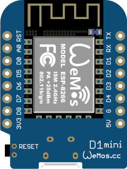
The Wemos D1 Mini is a versatile and compact development board that harnesses the power of the ESP8266 microcontroller. This board is widely used in the realm of Internet of Things (IoT) projects due to its small form factor, integrated Wi-Fi capabilities, and compatibility with the Arduino development environment. It is ideal for applications such as home automation, sensor networks, and DIY electronics projects.
Explore Projects Built with Wemos D1 Mini

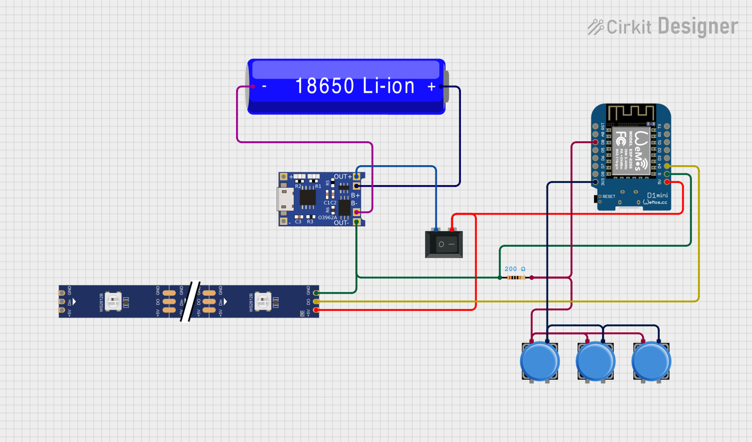
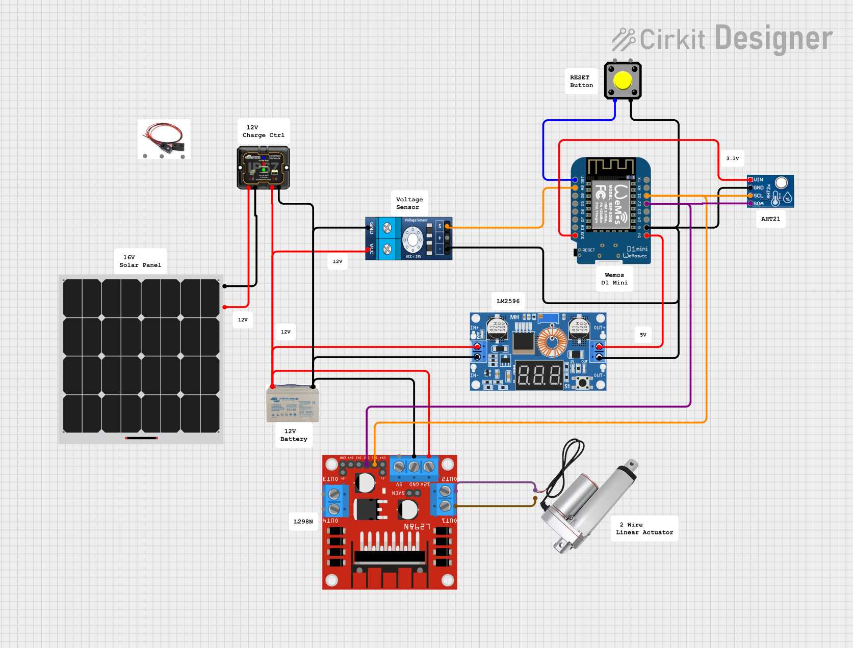
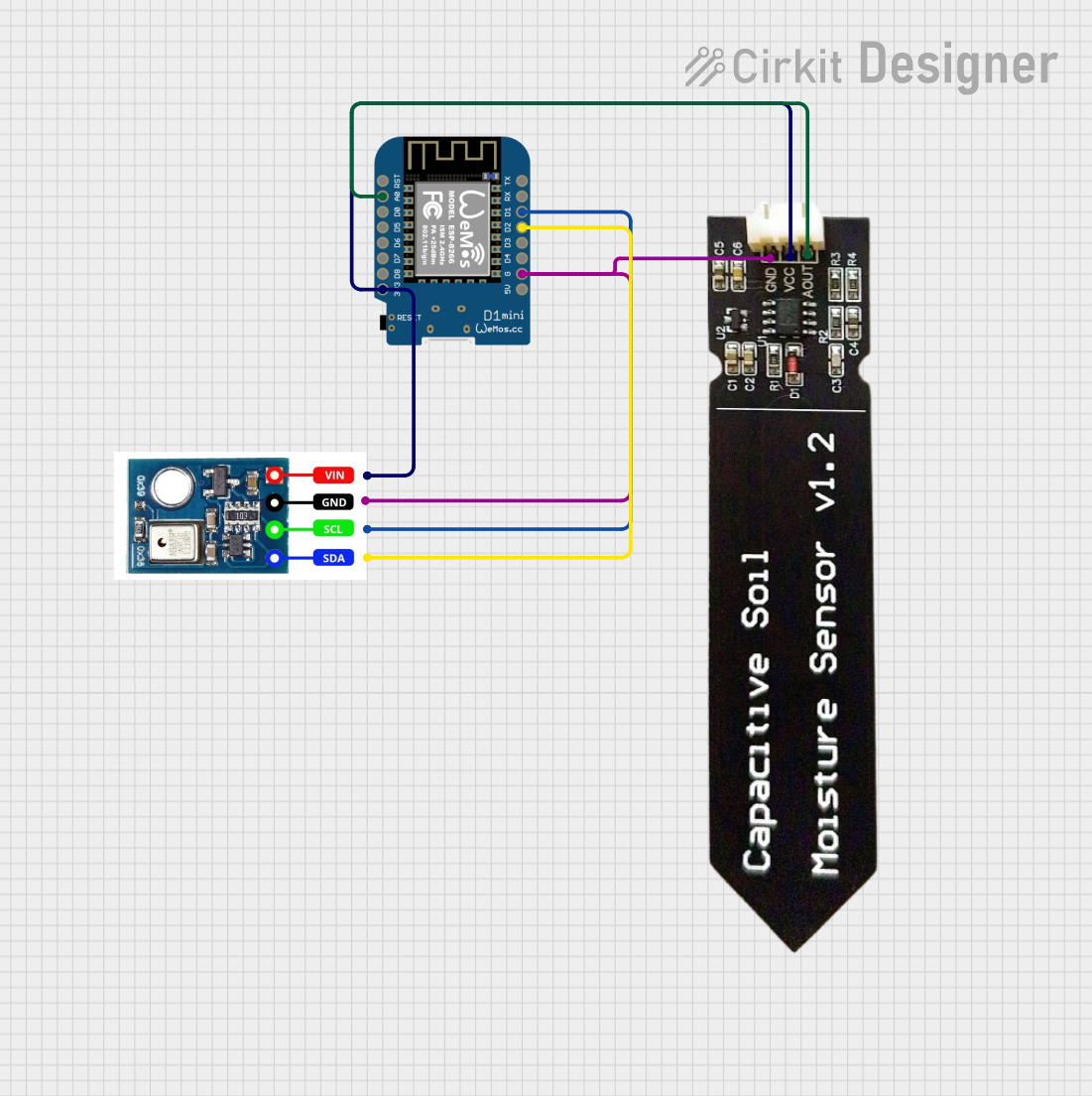
Explore Projects Built with Wemos D1 Mini
Technical Specifications
Key Features
- Microcontroller: ESP8266
- Operating Voltage: 3.3V
- Digital I/O Pins: 11
- Analog Input Pins: 1 (Max input: 3.2V)
- Clock Speed: 80/160MHz
- Flash Memory: 4MB
- Integrated Wi-Fi: 802.11 b/g/n
- USB-to-Serial Converter: CH340G
Pin Configuration
| Pin | Function | Description |
|---|---|---|
| D0 | GPIO16 | General-purpose I/O, can be used for deep sleep wake-up |
| D1 | GPIO5 | General-purpose I/O, often used for I2C SCL |
| D2 | GPIO4 | General-purpose I/O, often used for I2C SDA |
| D3 | GPIO0 | General-purpose I/O, pulled up, connected to FLASH button |
| D4 | GPIO2 | General-purpose I/O, pulled up, built-in LED |
| D5 | GPIO14 | General-purpose I/O, SPI SCK |
| D6 | GPIO12 | General-purpose I/O, SPI MISO |
| D7 | GPIO13 | General-purpose I/O, SPI MOSI |
| D8 | GPIO15 | General-purpose I/O, SPI SS, pulled to GND |
| RX | GPIO3 | RX pin, used for serial communication |
| TX | GPIO1 | TX pin, used for serial communication |
| A0 | ADC0 | Analog input, max 3.2V input |
| RST | RESET | Reset pin, pull low to reset the device |
| 3V3 | 3.3V power supply | |
| 5V | 5V power supply (USB or external) | |
| GND | Ground |
Usage Instructions
Setting Up the Wemos D1 Mini
- Install the USB Driver: Download and install the CH340G driver to enable USB-to-serial communication.
- Arduino IDE Configuration: In the Arduino IDE, go to
File > Preferencesand add the following URL to the "Additional Boards Manager URLs":http://arduino.esp8266.com/stable/package_esp8266com_index.json - Install the ESP8266 Board Package: Go to
Tools > Board > Boards Manager, search for "ESP8266", and install the package. - Select the Board: Choose "LOLIN(WEMOS) D1 R2 & mini" from
Tools > Boardmenu. - Select the Port: Select the COM port that the Wemos D1 Mini is connected to from
Tools > Port.
Basic Blink Example
// Define the LED_BUILTIN pin as the built-in LED pin
#define LED_BUILTIN D4

void setup() {
  pinMode(LED_BUILTIN, OUTPUT); // Initialize the LED pin as an output
}

void loop() {
  digitalWrite(LED_BUILTIN, LOW); // Turn the LED on
  delay(1000);                    // Wait for a second
  digitalWrite(LED_BUILTIN, HIGH); // Turn the LED off
  delay(1000);                     // Wait for a second
}
Important Considerations and Best Practices
- Power Supply: Ensure that the power supply is stable and within the recommended voltage range.
- I/O Pins: Do not exceed the maximum current rating for the I/O pins (12mA per pin).
- Analog Input: The maximum voltage for the A0 pin is 3.2V. Exceeding this voltage can damage the board.
- Firmware Flashing: When flashing new firmware, ensure that the correct settings are used to prevent bricking the device.
Troubleshooting and FAQs
Common Issues
- Board Not Recognized: Ensure that the CH340G USB driver is installed and the USB cable is functioning.
- Cannot Upload Sketch: Check the board and port settings in the Arduino IDE. Make sure the correct board is selected and the COM port is the one assigned to the Wemos D1 Mini.
- Wi-Fi Connection Issues: Verify the Wi-Fi credentials and signal strength. Ensure the board is within range of the Wi-Fi router.
FAQs
Q: Can I power the Wemos D1 Mini with 5V? A: Yes, you can power the board through the 5V pin or the USB port.
Q: How do I put the Wemos D1 Mini into deep sleep mode?
A: You can use the ESP.deepSleep(microseconds) function in your code. Connect D0 to RST to wake up the board.
Q: What is the maximum current the Wemos D1 Mini can supply to external components? A: The board can supply a maximum of 500mA through the 3.3V pin when powered via USB.
For further assistance, consult the Wemos D1 Mini community forums or the extensive online resources available for troubleshooting and project ideas.