
How to Use Linky Tri: Examples, Pinouts, and Specs
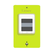
 Design with Linky Tri in Cirkit Designer
Introduction
The Linky Tri is a versatile triac-based electronic switch designed for controlling AC loads. It is widely used in applications requiring smooth dimming or speed control, such as lighting systems, ceiling fans, and motorized devices. Its ability to handle high AC voltages and currents makes it a reliable choice for both residential and industrial applications.
Explore Projects Built with Linky Tri
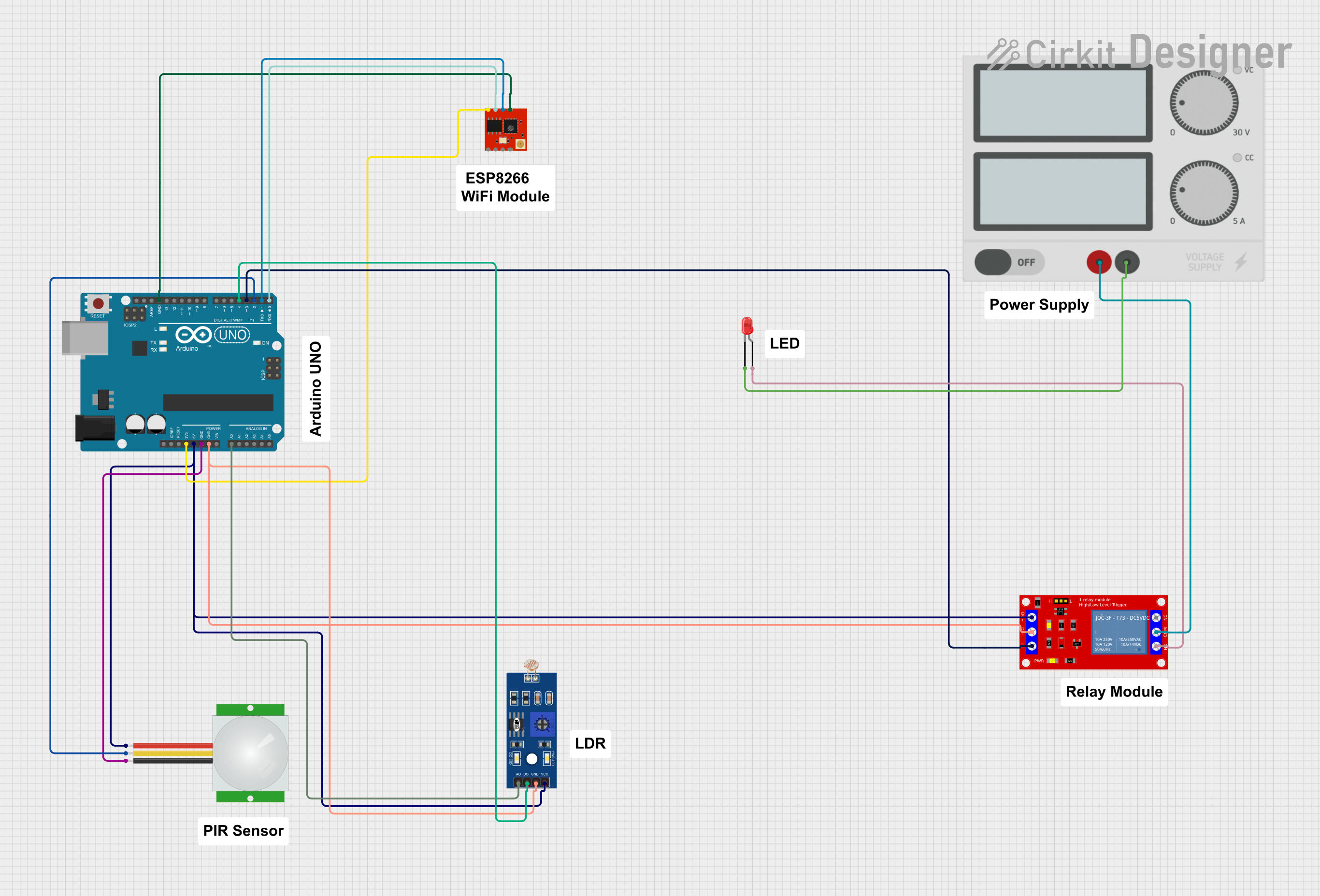 Open Project in Cirkit Designer
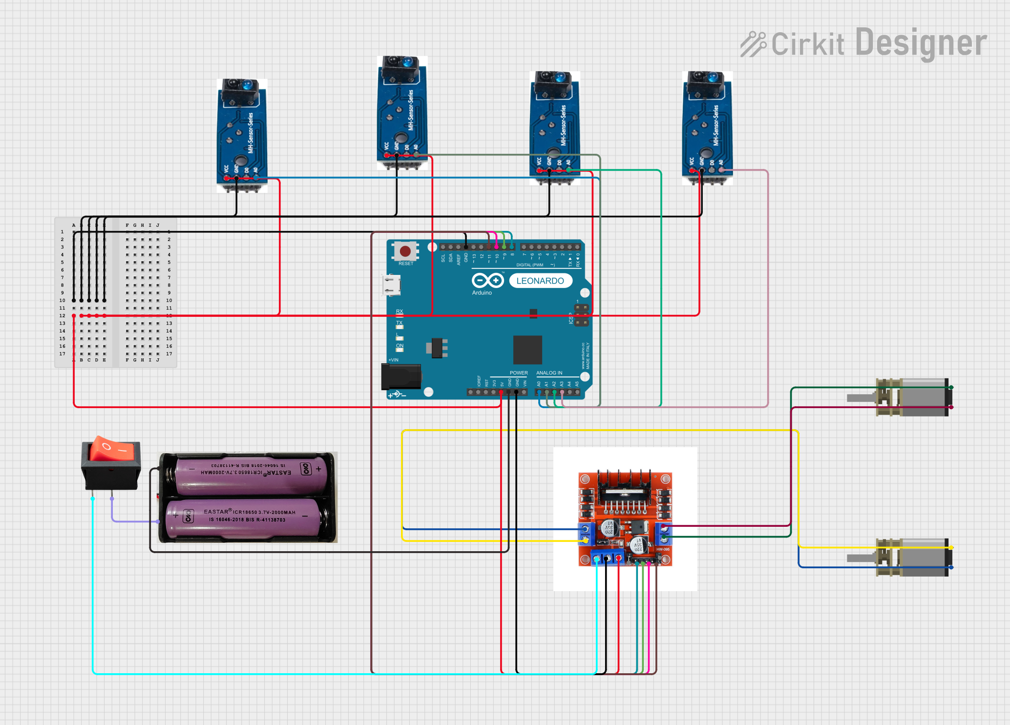 Open Project in Cirkit Designer
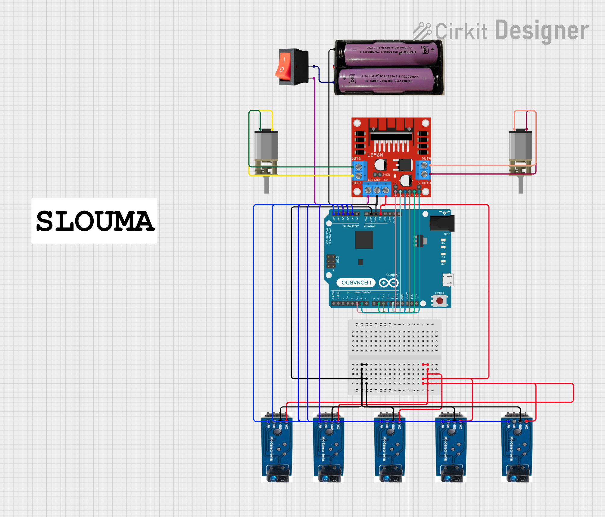 Open Project in Cirkit Designer
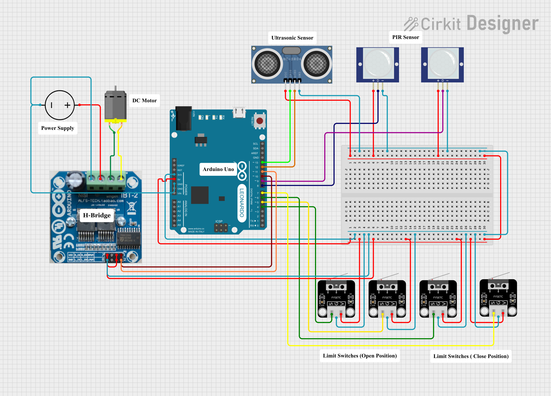 Open Project in Cirkit Designer
Explore Projects Built with Linky Tri
Open Project in Cirkit DesignerOpen Project in Cirkit DesignerOpen Project in Cirkit DesignerOpen Project in Cirkit DesignerCommon Applications
- Dimmable lighting systems
- Ceiling fan speed control
- Motorized appliances
- Industrial AC load management
- Home automation systems
Technical Specifications
Key Specifications
| Parameter | Value |
|---|---|
| Operating Voltage | 110V AC to 240V AC |
| Maximum Load Current | 10A |
| Control Voltage | 3.3V to 5V DC |
| Triggering Method | Gate triggering (triac-based) |
| Dimming Range | 0% to 100% |
| Isolation | Opto-isolated input |
| Operating Temperature | -20°C to 85°C |
| Dimensions | 50mm x 30mm x 15mm |
Pin Configuration
The Linky Tri has a simple pinout for easy integration into circuits. Below is the pin configuration:
| Pin Number | Pin Name | Description |
|---|---|---|
| 1 | AC Load 1 | Connect to one terminal of the AC load |
| 2 | AC Load 2 | Connect to the other terminal of the AC load |
| 3 | GND | Ground connection for the control circuit |
| 4 | VCC | Supply voltage for the control circuit (3.3V-5V) |
| 5 | Signal | Control signal input for triggering the triac |
Usage Instructions
How to Use the Linky Tri in a Circuit
- Power Supply: Connect the VCC pin to a 3.3V or 5V DC power source and the GND pin to the ground of your control circuit.
- AC Load Connection: Connect the AC load (e.g., a light bulb or motor) across the AC Load 1 and AC Load 2 pins.
- Control Signal: Use a microcontroller (e.g., Arduino UNO) or other control circuits to send a PWM or digital signal to the Signal pin. This signal will trigger the triac to control the AC load.
- Isolation: Ensure proper isolation between the control circuit and the AC load to prevent electrical hazards.
Important Considerations
- Heat Dissipation: The triac may generate heat during operation. Use a heatsink if operating at high currents.
- AC Voltage Safety: Always handle the AC connections with care to avoid electric shock.
- Signal Voltage: Ensure the control signal voltage matches the VCC level (3.3V or 5V).
- Load Compatibility: Verify that the load does not exceed the maximum current rating of 10A.
Example: Using Linky Tri with Arduino UNO
Below is an example of how to use the Linky Tri to control the brightness of an AC light bulb using an Arduino UNO.
Circuit Diagram
- Connect the AC load (light bulb) to the AC Load 1 and AC Load 2 pins.
- Connect the VCC and GND pins of the Linky Tri to the 5V and GND pins of the Arduino UNO.
- Connect the Signal pin of the Linky Tri to a PWM-capable pin on the Arduino UNO (e.g., Pin 9).
Arduino Code
// Example code to control Linky Tri with Arduino UNO
// This code uses PWM to dim an AC light bulb connected to Linky Tri

#define TRIAC_PIN 9  // Define the PWM pin connected to the Signal pin of Linky Tri

void setup() {
  pinMode(TRIAC_PIN, OUTPUT);  // Set the TRIAC_PIN as an output
}

void loop() {
  // Gradually increase brightness
  for (int brightness = 0; brightness <= 255; brightness++) {
    analogWrite(TRIAC_PIN, brightness);  // Send PWM signal to Linky Tri
    delay(10);  // Small delay for smooth dimming
  }

  // Gradually decrease brightness
  for (int brightness = 255; brightness >= 0; brightness--) {
    analogWrite(TRIAC_PIN, brightness);  // Send PWM signal to Linky Tri
    delay(10);  // Small delay for smooth dimming
  }
}
Best Practices
- Use a fuse in series with the AC load for added protection.
- Avoid operating the Linky Tri near its maximum current rating for prolonged periods.
- Test the circuit with a low-power load before connecting high-power devices.
Troubleshooting and FAQs
Common Issues and Solutions
| Issue | Possible Cause | Solution |
|---|---|---|
| AC load does not turn on | No control signal or incorrect wiring | Verify wiring and ensure proper signal |
| Flickering in dimmed state | Incorrect PWM frequency | Adjust the PWM frequency in the code |
| Overheating of the Linky Tri | Excessive load current | Use a heatsink or reduce the load current |
| No response to control signal | Signal voltage mismatch | Ensure the control signal matches VCC |
FAQs
Can I use the Linky Tri with a 3.3V microcontroller? Yes, the Linky Tri is compatible with both 3.3V and 5V control signals.
What type of loads can the Linky Tri control? The Linky Tri can control resistive loads (e.g., incandescent bulbs) and some inductive loads (e.g., motors). However, ensure the load does not exceed the maximum current rating.
Is the Linky Tri suitable for DC loads? No, the Linky Tri is designed specifically for AC loads.
How do I prevent electrical noise in the circuit? Use proper grounding and consider adding a snubber circuit across the triac to suppress electrical noise.
By following this documentation, you can effectively integrate the Linky Tri into your projects for reliable AC load control.