How to Use Red Cap Pushbutton: Examples, Pinouts, and Specs
Introduction
The Red Cap Pushbutton is a momentary switch that is activated when its red cap is pressed. It is commonly used in electronic devices to provide user input, such as triggering an event, resetting a system, or toggling a state. The button returns to its default position when released, making it ideal for applications requiring temporary activation.
Explore Projects Built with Red Cap Pushbutton


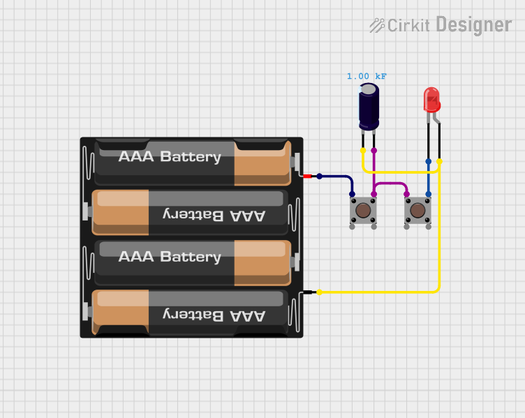
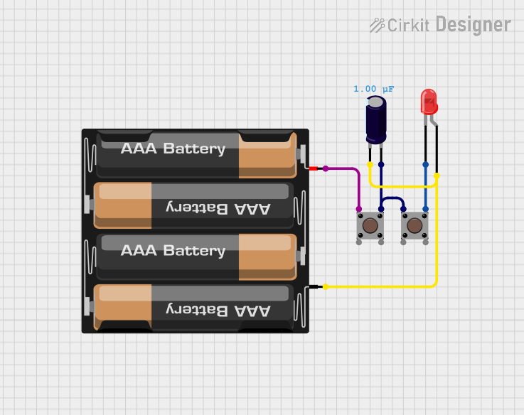
Explore Projects Built with Red Cap Pushbutton
Common Applications
- User input for microcontroller-based projects (e.g., Arduino, Raspberry Pi)
- Reset or power buttons in electronic devices
- Control panels for industrial or consumer electronics
- Prototyping and DIY electronics projects
Technical Specifications
The Red Cap Pushbutton is a simple, robust component with the following specifications:
| Parameter | Value |
|---|---|
| Operating Voltage | 3.3V to 12V |
| Maximum Current | 50mA |
| Contact Resistance | ≤ 50mΩ |
| Insulation Resistance | ≥ 100MΩ |
| Operating Temperature | -20°C to +70°C |
| Actuation Force | 150-200gf |
| Button Type | Momentary (Normally Open) |
| Dimensions | 12mm x 12mm x 7.3mm (approx) |
Pin Configuration
The Red Cap Pushbutton typically has four pins, arranged in a square pattern. However, only two pins are electrically active at any given time. The other two pins are duplicates for mechanical stability.
| Pin Number | Description |
|---|---|
| Pin 1 | Normally Open (NO) Contact |
| Pin 2 | Normally Open (NO) Contact |
| Pin 3 | Duplicate of Pin 1 (stability) |
| Pin 4 | Duplicate of Pin 2 (stability) |
Note: Pins 1 and 2 are internally connected to Pins 3 and 4, respectively. You can use either pair for your circuit.
Usage Instructions
How to Use the Red Cap Pushbutton in a Circuit
- Identify the Active Pins: Use a multimeter in continuity mode to identify the two active pins. When the button is pressed, these pins will show continuity.
- Connect to Circuit:
- Connect one active pin to the input signal or microcontroller pin.
- Connect the other active pin to ground (GND) or a pull-down resistor.
- Debounce the Button: Mechanical switches like the Red Cap Pushbutton may produce noise or "bouncing" when pressed. Use a capacitor (e.g., 0.1µF) or software debounce techniques to ensure stable operation.
Example: Connecting to an Arduino UNO
Below is an example of how to connect and use the Red Cap Pushbutton with an Arduino UNO:
Circuit Diagram
- Connect one active pin of the pushbutton to digital pin 2 on the Arduino.
- Connect the other active pin to GND.
- Use a 10kΩ pull-up resistor between digital pin 2 and 5V to ensure a stable HIGH signal when the button is not pressed.
Arduino Code
// Define the pin connected to the pushbutton
const int buttonPin = 2;  // Pin 2 is connected to the pushbutton
const int ledPin = 13;    // Pin 13 is connected to the onboard LED

void setup() {
  pinMode(buttonPin, INPUT_PULLUP); // Set button pin as input with internal pull-up
  pinMode(ledPin, OUTPUT);         // Set LED pin as output
}

void loop() {
  int buttonState = digitalRead(buttonPin); // Read the button state

  if (buttonState == LOW) { // Button is pressed (LOW due to pull-up resistor)
    digitalWrite(ledPin, HIGH); // Turn on the LED
  } else {
    digitalWrite(ledPin, LOW);  // Turn off the LED
  }
}
Best Practices
- Always use a pull-up or pull-down resistor to avoid floating input states.
- For long-term reliability, avoid exposing the button to excessive force or harsh environments.
- Use a debounce circuit or software to handle switch bouncing.
Troubleshooting and FAQs
Common Issues
Button Not Responding
- Cause: Incorrect pin connections or no pull-up/pull-down resistor.
- Solution: Verify the pin connections and ensure a pull-up or pull-down resistor is used.
Button Bouncing
- Cause: Mechanical noise from the switch contacts.
- Solution: Add a 0.1µF capacitor across the button pins or implement software debounce.
Intermittent Operation
- Cause: Loose connections or poor soldering.
- Solution: Check and secure all connections. Re-solder if necessary.
Button Always Reads as Pressed
- Cause: Short circuit or incorrect wiring.
- Solution: Inspect the circuit for shorts and verify the wiring.
FAQs
Q: Can I use the Red Cap Pushbutton with a 5V system?
A: Yes, the button is compatible with 5V systems. Ensure the current does not exceed 50mA.
Q: Do I need an external resistor if my microcontroller has internal pull-ups?
A: No, you can use the internal pull-up resistor by configuring the pin as INPUT_PULLUP in your code.
Q: How do I debounce the button in software?
A: Use a delay (e.g., 10-50ms) after detecting a button press to filter out bouncing. Alternatively, use a state machine or debounce library.
Q: Can I use the button for high-current applications?
A: No, the button is rated for a maximum current of 50mA. Use a relay or transistor for high-current switching.