Cirkit Designer Logo
Cirkit Designer
Your all-in-one circuit design IDE
Home / 
Component Documentation

How to Use Flame Sensor: Examples, Pinouts, and Specs

Image of Flame Sensor
Cirkit Designer LogoDesign with Flame Sensor in Cirkit Designer

Introduction

A flame sensor is a device that detects the presence of fire or flames by sensing infrared radiation emitted by the flame. It is commonly used in fire alarm systems and safety applications to provide early warning of fire hazards. Flame sensors are highly sensitive to infrared light within a specific wavelength range, making them effective for detecting open flames in various environments.

Explore Projects Built with Flame Sensor

Use Cirkit Designer to design, explore, and prototype these projects online. Some projects support real-time simulation. Click "Open Project" to start designing instantly!
Arduino UNO Based Multi-Flame Sensor Detection System
Image of flame sensor: A project utilizing Flame Sensor in a practical application
This circuit is designed to monitor for the presence of flames using three flame sensors connected to an Arduino UNO. Each flame sensor's analog output is connected to a separate analog input on the Arduino, allowing the microcontroller to read the intensity of the flame detected by each sensor. The 5V and GND pins of the Arduino provide power to the flame sensors.
Cirkit Designer LogoOpen Project in Cirkit Designer
Flame Detection and Automatic Water Pump Activation System
Image of FIRE: A project utilizing Flame Sensor in a practical application
This circuit features a heat flame sensor that likely triggers a response when detecting heat or flame. The sensor's digital output (DO) is connected through a resistor to a TIP41C transistor, which acts as a switch for a buzzer and a water pump, indicating that the circuit is designed to sound an alarm and possibly activate a water pump in the event of detecting a flame. The 9V battery powers the circuit, and all components share a common ground.
Cirkit Designer LogoOpen Project in Cirkit Designer
Arduino UNO-Based Environmental Monitoring System with Wi-Fi Connectivity
Image of fire and smoke detection: A project utilizing Flame Sensor in a practical application
This circuit is designed to monitor environmental conditions using a heat flame sensor and an MQ135 air quality sensor, display information on an LCD screen, and maintain accurate time with an RTC module. It includes an ESP8266 Wi-Fi module for potential wireless connectivity and uses a buzzer and LED for alerts or status indications. The Arduino UNO serves as the central controller, though the specific embedded code for operation is not yet provided.
Cirkit Designer LogoOpen Project in Cirkit Designer
Arduino UNO Based Gas and Flame Detection System with I2C LCD Feedback and Alert Buzzer
Image of SCHEMATIC DIAGRAM PROJECT 2: A project utilizing Flame Sensor in a practical application
This circuit features an Arduino UNO microcontroller connected to a heat flame sensor and an MQ-2 gas sensor for detecting flames and gases, respectively. The Arduino is also interfaced with an I2C LCD 16x2 screen for displaying sensor readings or status messages. Additionally, there is a buzzer connected to the Arduino, which can be used for audible alerts or alarms based on sensor inputs.
Cirkit Designer LogoOpen Project in Cirkit Designer

Explore Projects Built with Flame Sensor

Use Cirkit Designer to design, explore, and prototype these projects online. Some projects support real-time simulation. Click "Open Project" to start designing instantly!
Image of flame sensor: A project utilizing Flame Sensor in a practical application
Arduino UNO Based Multi-Flame Sensor Detection System
This circuit is designed to monitor for the presence of flames using three flame sensors connected to an Arduino UNO. Each flame sensor's analog output is connected to a separate analog input on the Arduino, allowing the microcontroller to read the intensity of the flame detected by each sensor. The 5V and GND pins of the Arduino provide power to the flame sensors.
Cirkit Designer LogoOpen Project in Cirkit Designer
Image of FIRE: A project utilizing Flame Sensor in a practical application
Flame Detection and Automatic Water Pump Activation System
This circuit features a heat flame sensor that likely triggers a response when detecting heat or flame. The sensor's digital output (DO) is connected through a resistor to a TIP41C transistor, which acts as a switch for a buzzer and a water pump, indicating that the circuit is designed to sound an alarm and possibly activate a water pump in the event of detecting a flame. The 9V battery powers the circuit, and all components share a common ground.
Cirkit Designer LogoOpen Project in Cirkit Designer
Image of fire and smoke detection: A project utilizing Flame Sensor in a practical application
Arduino UNO-Based Environmental Monitoring System with Wi-Fi Connectivity
This circuit is designed to monitor environmental conditions using a heat flame sensor and an MQ135 air quality sensor, display information on an LCD screen, and maintain accurate time with an RTC module. It includes an ESP8266 Wi-Fi module for potential wireless connectivity and uses a buzzer and LED for alerts or status indications. The Arduino UNO serves as the central controller, though the specific embedded code for operation is not yet provided.
Cirkit Designer LogoOpen Project in Cirkit Designer
Image of SCHEMATIC DIAGRAM PROJECT 2: A project utilizing Flame Sensor in a practical application
Arduino UNO Based Gas and Flame Detection System with I2C LCD Feedback and Alert Buzzer
This circuit features an Arduino UNO microcontroller connected to a heat flame sensor and an MQ-2 gas sensor for detecting flames and gases, respectively. The Arduino is also interfaced with an I2C LCD 16x2 screen for displaying sensor readings or status messages. Additionally, there is a buzzer connected to the Arduino, which can be used for audible alerts or alarms based on sensor inputs.
Cirkit Designer LogoOpen Project in Cirkit Designer

Common Applications and Use Cases

  • Fire alarm systems for residential, commercial, and industrial buildings
  • Gas stove and furnace flame monitoring
  • Firefighting robots and autonomous systems
  • Safety systems in hazardous environments
  • Early fire detection in outdoor or remote areas

Technical Specifications

Below are the key technical details of a typical flame sensor module:

Parameter Value
Operating Voltage 3.3V to 5V
Current Consumption 20mA (typical)
Detection Angle 60°
Wavelength Sensitivity 760 nm to 1100 nm (infrared range)
Output Type Digital (D0) and Analog (A0)
Operating Temperature -25°C to 85°C

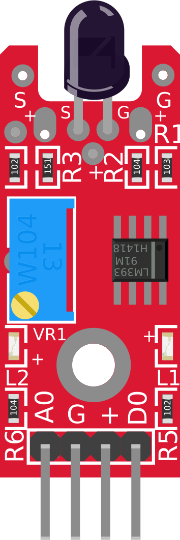
Pin Configuration and Descriptions

Pin Name Description
1 VCC Connect to the positive power supply (3.3V to 5V).
2 GND Connect to the ground of the power supply.
3 D0 Digital output pin. Outputs HIGH when flame is detected, LOW otherwise.
4 A0 Analog output pin. Provides a variable voltage proportional to flame intensity.

Usage Instructions

How to Use the Flame Sensor in a Circuit

  1. Power the Sensor: Connect the VCC pin to a 3.3V or 5V power supply and the GND pin to ground.
  2. Connect Outputs:
    • Use the D0 pin for digital output. It will output HIGH (logic 1) when a flame is detected and LOW (logic 0) otherwise.
    • Use the A0 pin for analog output. This pin provides a voltage proportional to the intensity of the detected flame.
  3. Adjust Sensitivity: Use the onboard potentiometer to adjust the sensitivity of the sensor. Turn it clockwise to increase sensitivity and counterclockwise to decrease it.
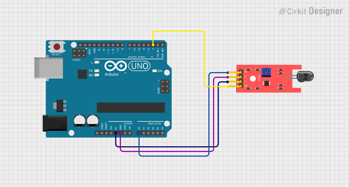
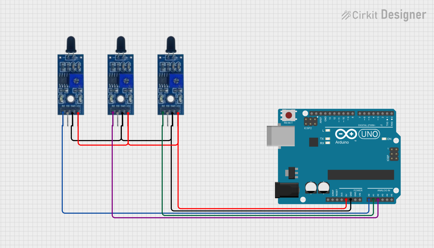
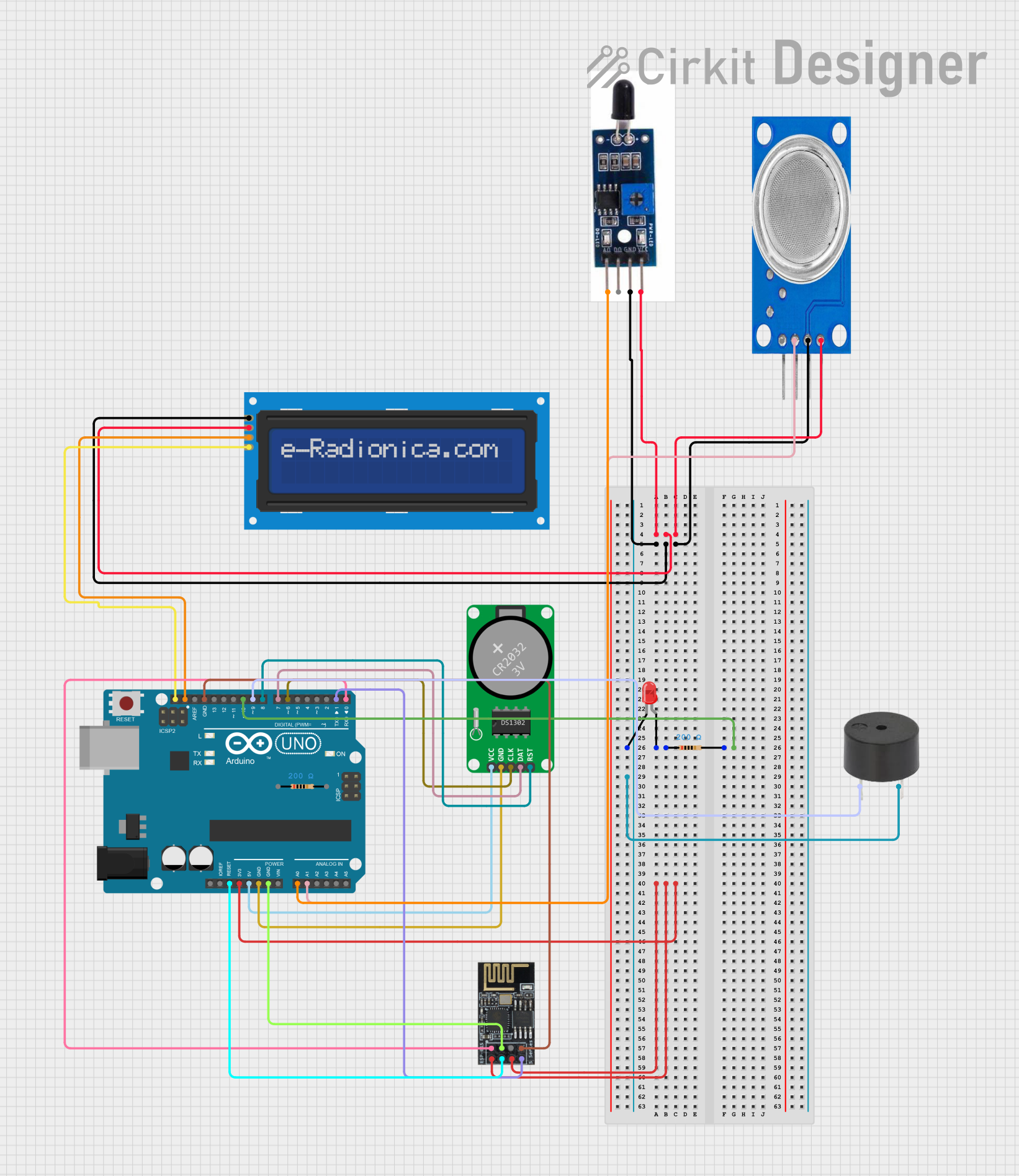
  4. Integrate with a Microcontroller: Connect the output pins (D0 or A0) to a microcontroller, such as an Arduino UNO, for further processing.

Important Considerations and Best Practices

  • Avoid False Positives: Ensure the sensor is not exposed to other infrared sources, such as sunlight or incandescent bulbs, which may cause false detections.
  • Placement: Position the sensor with a clear line of sight to the flame for accurate detection.
  • Power Supply: Use a stable power supply to avoid fluctuations that may affect sensor performance.
  • Testing: Test the sensor in a controlled environment before deploying it in critical applications.

Example Code for Arduino UNO

Below is an example of how to use the flame sensor with an Arduino UNO:

// Define the pins for the flame sensor
const int flameSensorDigitalPin = 2; // Digital output pin (D0)
const int flameSensorAnalogPin = A0; // Analog output pin (A0)
const int ledPin = 13; // Built-in LED for flame detection indication

void setup() {
  pinMode(flameSensorDigitalPin, INPUT); // Set D0 as input
  pinMode(ledPin, OUTPUT); // Set LED pin as output
  Serial.begin(9600); // Initialize serial communication for debugging
}

void loop() {
  int flameDigital = digitalRead(flameSensorDigitalPin); // Read digital output
  int flameAnalog = analogRead(flameSensorAnalogPin); // Read analog output

  // Print analog value to the Serial Monitor
  Serial.print("Analog Value: ");
  Serial.println(flameAnalog);

  // Check if a flame is detected
  if (flameDigital == HIGH) {
    digitalWrite(ledPin, HIGH); // Turn on LED if flame is detected
    Serial.println("Flame detected!");
  } else {
    digitalWrite(ledPin, LOW); // Turn off LED if no flame is detected
    Serial.println("No flame detected.");
  }

  delay(500); // Wait for 500ms before the next reading
}

Troubleshooting and FAQs

Common Issues and Solutions

  1. No Flame Detection:

    • Cause: Incorrect wiring or insufficient power supply.
    • Solution: Double-check the connections and ensure the sensor is powered with 3.3V to 5V.
  2. False Positives:

    • Cause: Exposure to other infrared sources (e.g., sunlight, incandescent bulbs).
    • Solution: Shield the sensor from external IR sources or adjust its sensitivity using the potentiometer.
  3. Unstable Readings:

    • Cause: Electrical noise or unstable power supply.
    • Solution: Use decoupling capacitors near the sensor's power pins to stabilize the voltage.
  4. Analog Output Not Changing:

    • Cause: Flame is too far or not within the sensor's detection angle.
    • Solution: Ensure the flame is within the 60° detection angle and within a reasonable distance.

FAQs

Q1: Can the flame sensor detect flames through glass?
A1: No, most flame sensors cannot detect flames through glass as it blocks infrared radiation.

Q2: What is the maximum distance for flame detection?
A2: The detection range depends on the flame size and intensity but is typically up to 1 meter.

Q3: Can I use the flame sensor outdoors?
A3: Yes, but ensure it is protected from environmental factors like rain, dust, and direct sunlight to avoid damage or false readings.

Q4: How do I know if the sensor is working?
A4: Test the sensor by exposing it to a small flame (e.g., a lighter) and observe the digital output (D0) or analog output (A0) values.