How to Use Arduino 101: Examples, Pinouts, and Specs
Introduction
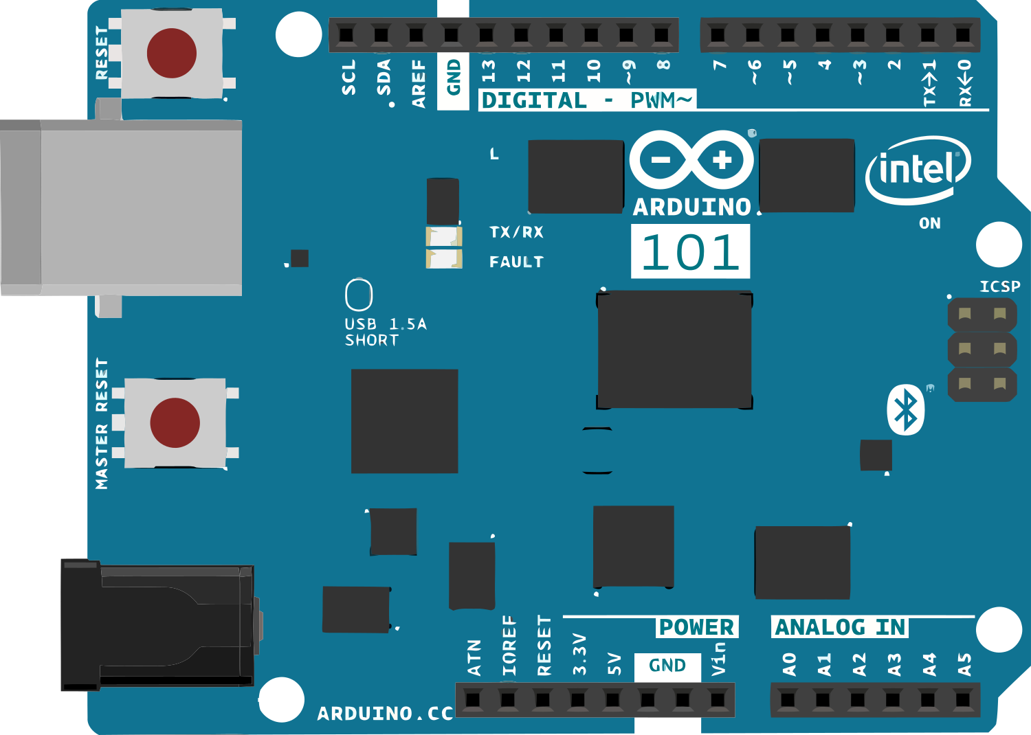
The Arduino 101 is a versatile microcontroller board that integrates the Intel Curie module, which is designed for the Internet of Things (IoT) and wearable technology applications. It features a dual-core Intel Quark processor along with Bluetooth Low Energy (BLE) connectivity, a six-axis accelerometer, and a gyroscope. The board is compatible with a wide range of Arduino shields and accessories, making it an excellent choice for hobbyists, educators, and professionals looking to develop interactive projects.
Explore Projects Built with Arduino 101

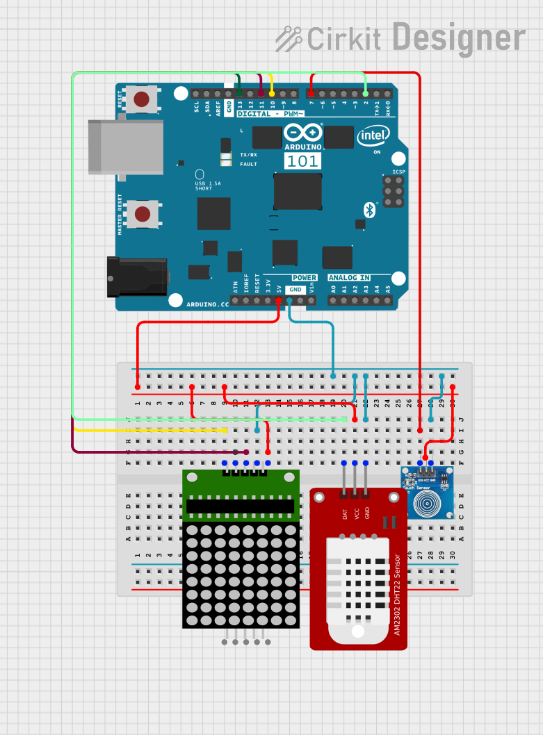
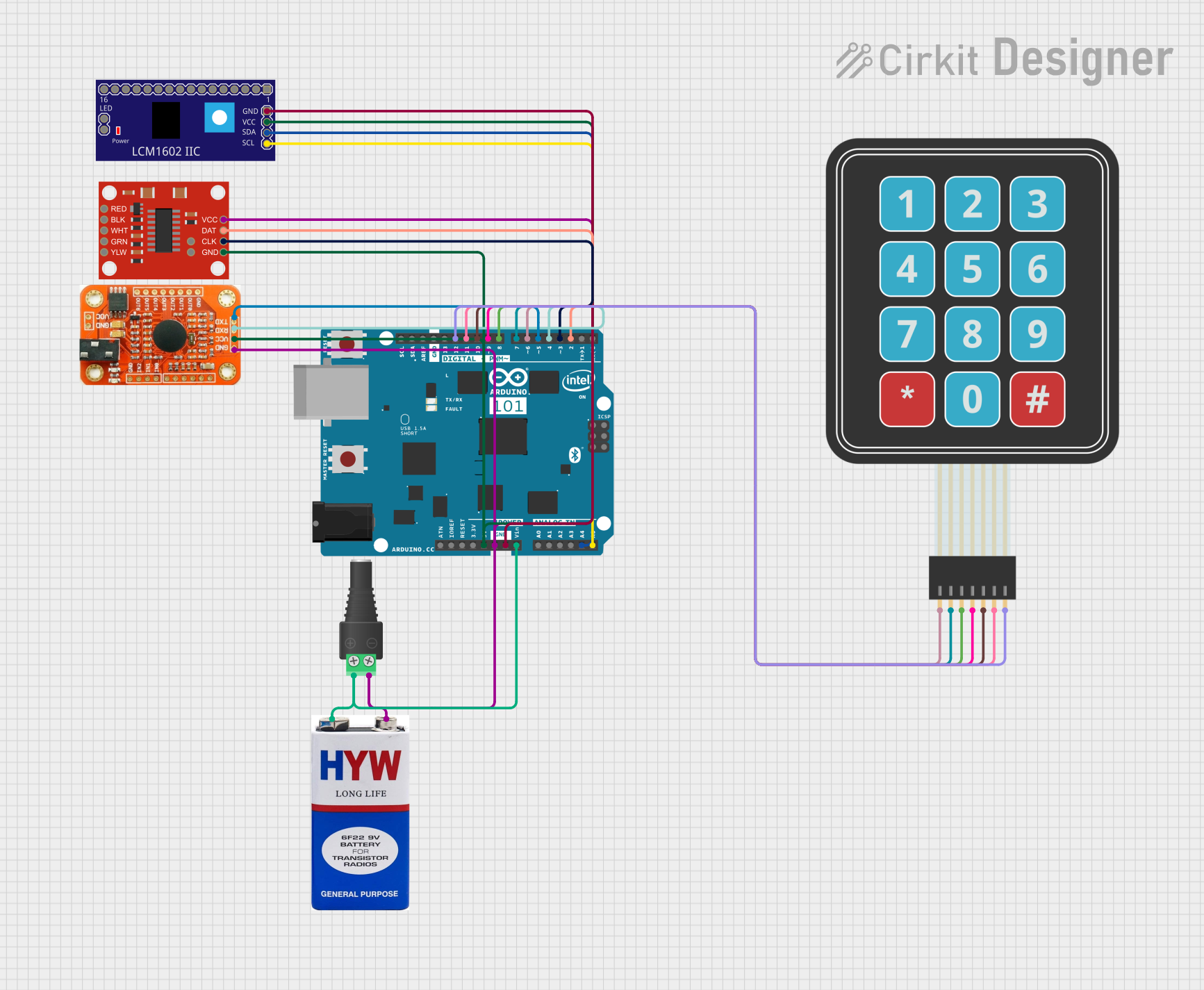
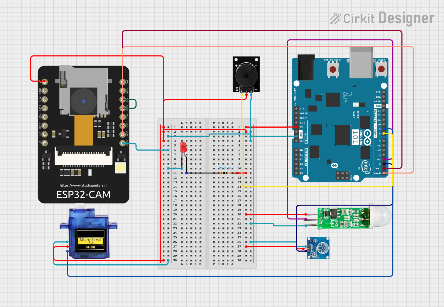
Explore Projects Built with Arduino 101
Common Applications and Use Cases
- IoT devices
- Wearable technology
- Educational projects
- Prototyping for embedded systems
- Robotics
- Wireless sensor networks
Technical Specifications
Key Technical Details
- Microcontroller: Intel Curie
- Operating Voltage: 3.3V
- Input Voltage (recommended): 7-12V
- Input Voltage (limit): 6-20V
- Digital I/O Pins: 14 (of which 4 provide PWM output)
- Analog Input Pins: 6
- DC Current per I/O Pin: 20 mA
- Flash Memory: 196 kB
- SRAM: 24 kB
- Clock Speed: 32 MHz
- Bluetooth LE: Built-in
Pin Configuration and Descriptions
| Pin Number | Function | Description |
|---|---|---|
| 0 | RX | Serial Receive |
| 1 | TX | Serial Transmit |
| 2-13 | Digital I/O | Digital Input/Output, PWM on pins 3,5,6,9 |
| A0-A5 | Analog Input | Analog Input Channels |
| AREF | Analog Ref | Reference voltage for the analog inputs |
| GND | Ground | Ground pin |
| RST | Reset | Resets the microcontroller |
| 3.3V | 3.3V Supply | 3.3V power supply pin |
| VIN | Voltage Input | Unregulated input voltage to the Arduino 101 |
Usage Instructions
How to Use the Arduino 101 in a Circuit
- Powering the Board: The Arduino 101 can be powered via the USB connection or with an external power supply. The power source is selected automatically.
- Connecting to a Computer: Connect the board to your computer using a USB cable to upload sketches and communicate with the board.
- Writing a Sketch: Use the Arduino IDE to write your code (sketches) and upload it to the board.
- Interfacing with Sensors and Actuators: Connect sensors to the analog pins and actuators to the digital I/O pins, taking care not to exceed the current limits.
Important Considerations and Best Practices
- Always disconnect the Arduino 101 from power sources before making or altering connections.
- Ensure that the voltage levels of peripherals are compatible with the Arduino 101's 3.3V logic.
- Use external power supplies when connecting components that draw more current than the USB can provide.
- Avoid exposing the board to static electricity, which can damage the microcontroller.
Troubleshooting and FAQs
Common Issues
- Sketch not uploading: Check the USB cable and port, ensure the correct board and port are selected in the Arduino IDE.
- Board not recognized by computer: Install the latest drivers and reset the board.
- Inconsistent behavior: Ensure that the power supply is adequate and stable.
Solutions and Tips for Troubleshooting
- Reset the Board: Press the reset button on the board to restart the microcontroller.
- Check Connections: Loose connections can cause unexpected behavior. Double-check all connections.
- Update Firmware: Ensure the board's firmware is up to date for optimal performance.
FAQs
Q: Can the Arduino 101 be powered by a battery? A: Yes, it can be powered by a battery connected to the VIN pin, within the 6-20V limit.
Q: Is the Arduino 101 compatible with all Arduino shields? A: Most shields designed for the Arduino Uno will work with the Arduino 101, but check for 3.3V compatibility.
Q: How do I use Bluetooth functionality? A: The Arduino 101 includes built-in BLE. Use the CurieBLE library in the Arduino IDE to develop Bluetooth applications.
Example Code for Arduino UNO
Here's a simple example of how to blink an LED connected to pin 13 on the Arduino 101:
// Pin 13 has an LED connected on most Arduino boards.
int led = 13;

// The setup routine runs once when you press reset:
void setup() {
  // Initialize the digital pin as an output.
  pinMode(led, OUTPUT);
}

// The loop routine runs over and over again forever:
void loop() {
  digitalWrite(led, HIGH);   // Turn the LED on (HIGH is the voltage level)
  delay(1000);               // Wait for a second
  digitalWrite(led, LOW);    // Turn the LED off by making the voltage LOW
  delay(1000);               // Wait for a second
}
Remember to keep the code comments concise and within the 80-character line length limit.