A terminal block is a modular, insulated block designed to secure two or more wires together. It provides a convenient and reliable way to connect and disconnect electrical circuits without the need for soldering. Terminal blocks are widely used in electrical and electronic systems for organizing and managing wiring connections. They are available in various sizes, configurations, and current ratings to suit different applications.
Explore Projects Built with Terminal Block
Use Cirkit Designer to design, explore, and prototype these projects online. Some projects support real-time simulation. Click "Open Project" to start designing instantly!
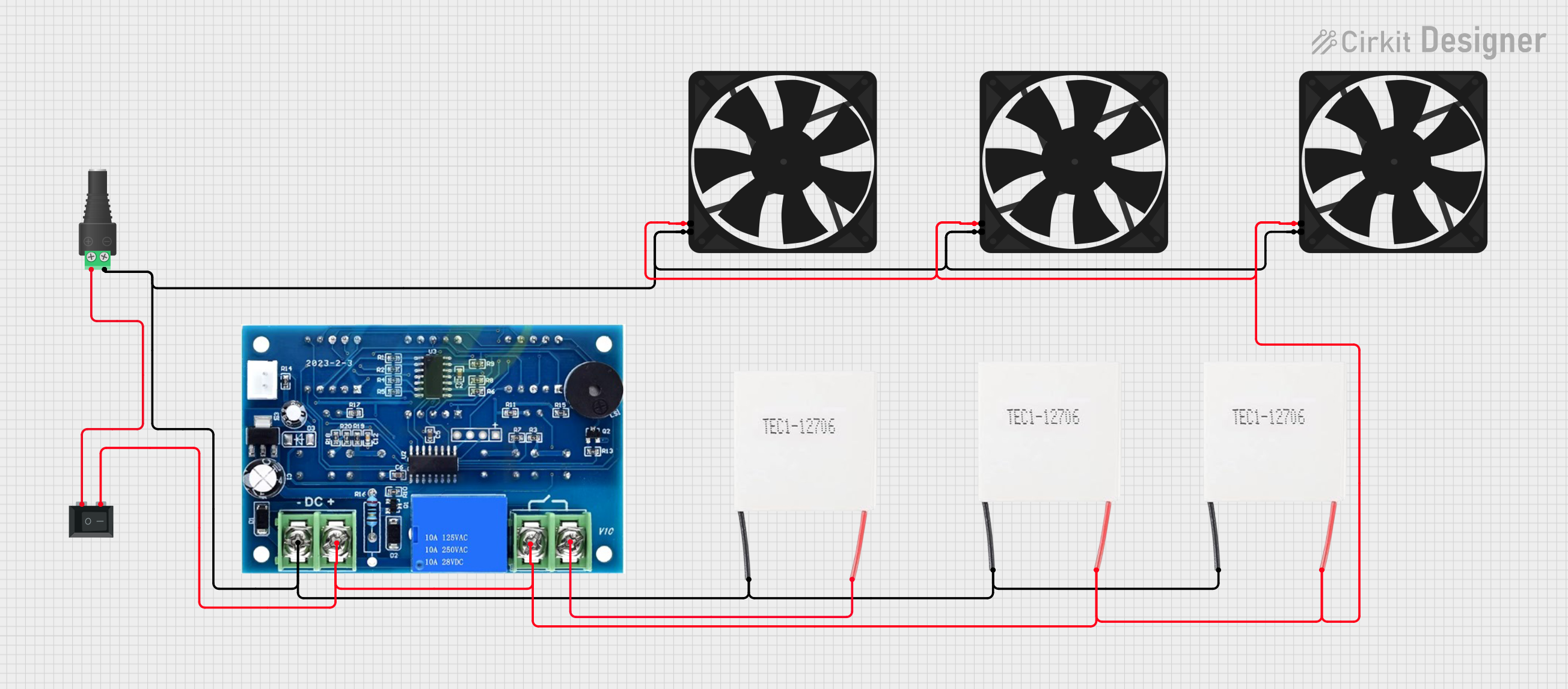
This circuit consists of multiple Peltier modules and fans connected in parallel to a digital power supply, with a rocker switch (SPST) controlling the power flow to one of the Peltier modules and multiple fans. The 2.1mm Barrel Jack with Terminal Block serves as the power input connector, and the rocker switch allows for selective enabling or disabling of the connected devices. The circuit is designed to provide cooling or heating through the Peltier modules while the fans assist in heat dissipation or air circulation.
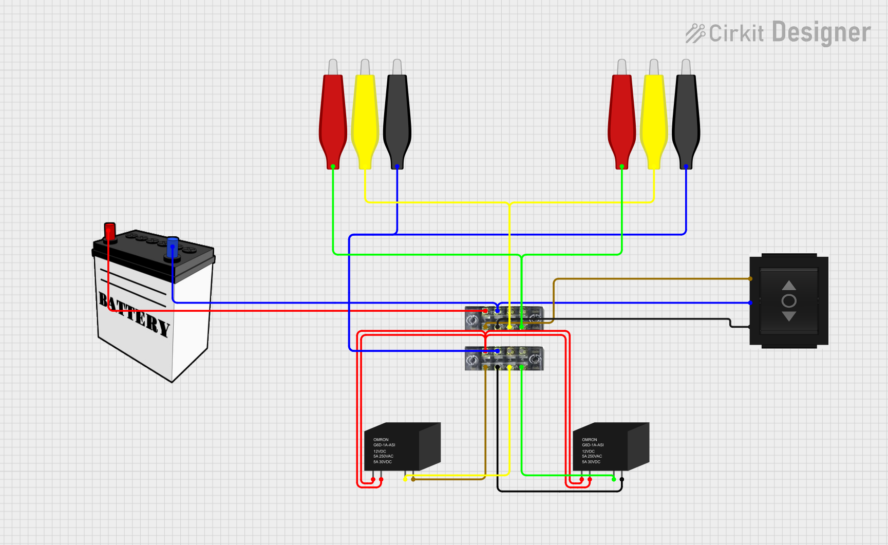
This circuit involves a 12V battery powering a relay system controlled by a directional switch. The relays are connected through terminal blocks and are used to switch between different outputs, indicated by the AdaGator Top components.
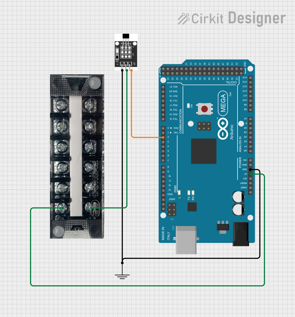
This circuit uses an Arduino Mega 2560 to read data from a Hall Sensor, which is powered through a terminal block connected to the Arduino's 5V supply. The sensor's ground is connected to the Arduino's ground, and its signal output is read by the Arduino on pin D2.
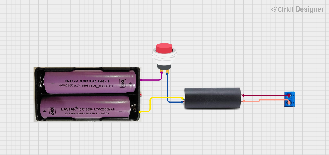
This circuit features a high voltage generator connected to a terminal PCB for output, with its power supply controlled by a 2-pin push switch. The high voltage generator's VCC is connected through the switch, allowing the user to turn the high voltage output on and off. The circuit is powered by a 7.4V battery, with the positive terminal connected to the switch and the negative terminal connected to the generator's ground.
The specifications of a terminal block can vary depending on its type and application. Below are the general technical details for a standard screw-type terminal block:
Key Technical Details
Voltage Rating: Up to 600V (varies by model)
Current Rating: 10A to 150A (depending on size and type)
Wire Gauge Compatibility: 22 AWG to 2 AWG
Insulation Material: Polyamide (PA66) or other flame-retardant materials
Operating Temperature: -40°C to +105°C
Mounting Type: DIN rail, PCB mount, or panel mount
Connection Type: Screw, spring clamp, or push-in
Pin Configuration and Descriptions
Terminal blocks do not have "pins" in the traditional sense but instead feature connection points for wires. Below is a table describing the key parts of a screw-type terminal block:
Part
Description
Screw Terminal
Secures the wire in place by tightening a screw.
Wire Insertion Hole
The opening where the wire is inserted.
Insulation Barrier
Prevents electrical contact between adjacent terminals.
Mounting Base
The base used to attach the terminal block to a panel, PCB, or DIN rail.
Labeling Area
Space for marking or labeling connections for easy identification.
Usage Instructions
How to Use the Terminal Block in a Circuit
Prepare the Wires:
Strip the insulation from the end of each wire (typically 5-10mm, depending on the terminal block size).
Ensure the wire strands are twisted or use ferrules to prevent fraying.
Insert the Wires:
Loosen the screw on the terminal block to open the wire insertion hole.
Insert the stripped end of the wire into the hole.
Secure the Connection:
Tighten the screw to clamp the wire securely in place.
Avoid overtightening, as this may damage the wire or terminal block.
Connect to the Circuit:
Repeat the process for all wires, ensuring proper polarity and alignment.
Use the labeling area to mark connections for easy identification.
Test the Connection:
Verify the connections using a multimeter to ensure continuity and proper wiring.
Important Considerations and Best Practices
Wire Compatibility: Always check the wire gauge compatibility of the terminal block before use.
Tightening Torque: Follow the manufacturer's recommended torque specifications to avoid damaging the terminal block or wires.
Insulation Check: Ensure no exposed wire is visible outside the terminal block to prevent short circuits.
Environmental Conditions: Use terminal blocks rated for the operating temperature and environmental conditions of your application.
Safety: Disconnect power before making or modifying connections.
Example: Connecting a Terminal Block to an Arduino UNO
While terminal blocks are not directly connected to an Arduino UNO, they can be used to organize and distribute power or signals in a circuit. Below is an example of using a terminal block to distribute power to multiple devices:
// Example: Distributing 5V power from Arduino UNO to multiple devices
// through a terminal block

// No specific code is required for the terminal block itself, as it is a
// passive component. However, ensure the Arduino's 5V pin is connected
// to the terminal block, and the devices are connected to the other
// terminals.

void setup() {
  // Initialize any connected devices here
  // For example, sensors or modules powered via the terminal block
}

void loop() {
  // Main program logic
}
Troubleshooting and FAQs
Common Issues and Solutions
Issue
Solution
Loose connections
Ensure the screws are tightened properly and the wires are securely clamped.
Wire fraying or slipping out
Use ferrules or twist the wire strands before inserting them.
Overheating of terminal block
Check the current rating and ensure it is not exceeded.
Short circuits between adjacent terminals
Verify that the insulation barriers are intact and wires are properly inserted.
Difficulty inserting wires
Ensure the screws are loosened enough to allow wire insertion.
FAQs
Can terminal blocks handle high currents?
Yes, but you must select a terminal block with an appropriate current rating for your application.
Are terminal blocks reusable?
Yes, terminal blocks can be reused as long as they are not damaged or worn out.
What is the difference between screw and spring clamp terminal blocks?
Screw terminal blocks use screws to secure wires, while spring clamp terminal blocks use a spring mechanism for faster and tool-free connections.
Can terminal blocks be used outdoors?
Only if they are rated for outdoor use and protected against moisture and environmental factors.
How do I choose the right terminal block for my project?
Consider factors such as voltage and current ratings, wire gauge compatibility, mounting type, and environmental conditions.


 Open Project in Cirkit Designer