How to Use MTS_230_2P: Examples, Pinouts, and Specs
Introduction
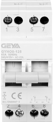
The MTS_230_2P is a two-pole miniature circuit breaker (MCB) designed to provide overcurrent protection in electrical circuits. It automatically disconnects the circuit when it detects excessive current, safeguarding electrical devices and reducing the risk of fire hazards. This component is widely used in residential, commercial, and industrial electrical systems to ensure safety and reliability.
Explore Projects Built with MTS_230_2P


Explore Projects Built with MTS_230_2P
Common Applications
- Protection of electrical circuits in homes, offices, and industrial facilities.
- Prevention of damage to sensitive electrical equipment due to overcurrent.
- Use in distribution boards and panel boards for circuit isolation.
- Overload and short-circuit protection in lighting and power circuits.
Technical Specifications
The following table outlines the key technical details of the MTS_230_2P:
| Parameter | Specification |
|---|---|
| Rated Voltage | 230/400 V AC |
| Rated Current | 6 A, 10 A, 16 A, 20 A, 25 A, 32 A |
| Number of Poles | 2 |
| Breaking Capacity | 6 kA |
| Tripping Curve | B, C, or D (depending on model) |
| Frequency | 50/60 Hz |
| Operating Temperature | -5°C to +40°C |
| Mounting Type | DIN Rail (35 mm) |
| Terminal Type | Screw terminals |
| Housing Material | Flame-retardant thermoplastic |
| Dimensions (L x W x H) | 81 mm x 36 mm x 68 mm |
| Weight | ~200 g |
Pin Configuration and Descriptions
The MTS_230_2P does not have traditional pins like an IC but instead features screw terminals for electrical connections. The table below describes the terminal configuration:
| Terminal | Description |
|---|---|
| L1 | Input terminal for the first live wire (Phase 1). |
| L2 | Input terminal for the second live wire (Phase 2). |
| T1 | Output terminal for the first live wire (Phase 1) after protection. |
| T2 | Output terminal for the second live wire (Phase 2) after protection. |
Usage Instructions
How to Use the MTS_230_2P in a Circuit
- Mounting: Secure the MTS_230_2P onto a standard 35 mm DIN rail in the distribution board.
- Wiring:
- Connect the incoming live wires (Phase 1 and Phase 2) to the input terminals L1 and L2.
- Connect the outgoing live wires to the output terminals T1 and T2.
- Ensure all connections are tight to avoid loose contacts.
- Power On: After wiring, switch on the circuit breaker by flipping the lever to the "ON" position.
- Testing: Test the breaker by simulating an overcurrent condition (if safe to do so) to ensure it trips correctly.
Important Considerations
- Current Rating: Select the appropriate current rating (e.g., 10 A, 16 A) based on the load requirements of your circuit.
- Tripping Curve: Choose the correct tripping curve (B, C, or D) depending on the type of load:
- B Curve: For resistive loads (e.g., lighting, heating).
- C Curve: For inductive loads (e.g., motors, transformers).
- D Curve: For high inrush current loads (e.g., large motors).
- Safety: Always disconnect the power supply before installing or servicing the breaker.
- Compatibility: Ensure the breaker is compatible with the voltage and frequency of your electrical system.
Arduino Integration
The MTS_230_2P is not directly compatible with Arduino or other microcontrollers, as it is a high-voltage component designed for AC circuits. However, it can be used in conjunction with relays or contactors controlled by an Arduino to manage high-power loads safely.
Troubleshooting and FAQs
Common Issues and Solutions
| Issue | Possible Cause | Solution |
|---|---|---|
| Circuit breaker trips frequently | Overloaded circuit or short circuit | Reduce the load or check for wiring faults. |
| Breaker does not trip during overcurrent | Faulty breaker or incorrect current rating | Replace the breaker or select the correct current rating for the circuit. |
| Loose connections | Improperly tightened terminal screws | Ensure all terminal screws are securely tightened. |
| Breaker lever stuck in "OFF" position | Internal mechanism damaged or fault detected | Replace the breaker if it is damaged or inspect the circuit for faults. |
FAQs
Can the MTS_230_2P be used for DC circuits?
- No, the MTS_230_2P is designed for AC circuits only. For DC applications, use a DC-rated circuit breaker.
What is the difference between B, C, and D tripping curves?
- The tripping curve determines the sensitivity of the breaker to overcurrent:
- B Curve: Trips at 3-5 times the rated current.
- C Curve: Trips at 5-10 times the rated current.
- D Curve: Trips at 10-20 times the rated current.
- The tripping curve determines the sensitivity of the breaker to overcurrent:
How do I know if the breaker is faulty?
- If the breaker does not trip during an overcurrent condition or trips without any load, it may be faulty and should be replaced.
Can I use the MTS_230_2P for single-phase circuits?
- Yes, you can use it for single-phase circuits by connecting only one pole, but this is not recommended as it is designed for two-pole operation.
By following this documentation, users can safely and effectively integrate the MTS_230_2P into their electrical systems.