Cirkit Designer Logo
Cirkit Designer
Your all-in-one circuit design IDE
Home / 
Component Documentation

How to Use TP-Link JetStream (TL-SG2016P): Examples, Pinouts, and Specs

Image of TP-Link JetStream (TL-SG2016P)
Cirkit Designer LogoDesign with TP-Link JetStream (TL-SG2016P) in Cirkit Designer

Introduction

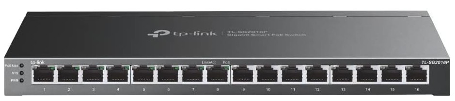
The TP-Link JetStream (TL-SG2016P) is a managed Ethernet switch equipped with 16 Gigabit ports, 8 of which support Power over Ethernet (PoE). This device is designed to deliver high-speed data transfer, efficient network management, and reliable power delivery to connected devices. It is an ideal solution for small to medium-sized business environments, enabling seamless integration of IP cameras, VoIP phones, wireless access points, and other networked devices.

Explore Projects Built with TP-Link JetStream (TL-SG2016P)

Use Cirkit Designer to design, explore, and prototype these projects online. Some projects support real-time simulation. Click "Open Project" to start designing instantly!
Satellite Compass and Network-Integrated GPS Data Processing System
Image of GPS 시스템 측정 구성도_241016: A project utilizing TP-Link JetStream (TL-SG2016P) in a practical application
This circuit comprises a satellite compass, a mini PC, two GPS antennas, power supplies, a network switch, media converters, and an atomic rubidium clock. The satellite compass is powered by a triple output DC power supply and interfaces with an RS232 splitter for 1PPS signals. The mini PCs are connected to the USRP B200 devices via USB for data and power, and to media converters via Ethernet, which in turn connect to a network switch using fiber optic links. The antennas are connected to the USRP B200s through RF directional couplers, and the atomic clock provides a 1PPS input to the RS232 splitter.
Cirkit Designer LogoOpen Project in Cirkit Designer
Satellite-Based Timing and Navigation System with SDR and Atomic Clock Synchronization
Image of GPS 시스템 측정 구성도_Confirm: A project utilizing TP-Link JetStream (TL-SG2016P) in a practical application
This circuit appears to be a complex system involving power supply management, GPS and timing synchronization, and data communication. It includes a SI-TEX G1 Satellite Compass for GPS data, an XHTF1021 Atomic Rubidium Clock for precise timing, and Ettus USRP B200 units for software-defined radio communication. Power is supplied through various SMPS units and distributed via terminal blocks and DC jacks. Data communication is facilitated by Beelink MINI S12 N95 computers, RS232 splitters, and a 1000BASE-T Media Converter for network connectivity. RF Directional Couplers are used to interface antennas with the USRP units, and the entire system is likely contained within cases for protection and organization.
Cirkit Designer LogoOpen Project in Cirkit Designer
ESP8266 NodeMCU with LoRa and RS-485 Communication and Ethernet Connectivity
Image of Wiring Diagram LoRa: A project utilizing TP-Link JetStream (TL-SG2016P) in a practical application
This circuit serves as a multi-protocol communication hub featuring two ESP8266 NodeMCUs for processing, each connected to a LoRa Ra-02 SX1278 for long-range wireless communication. One NodeMCU is also connected to an RS-485 module for serial communication and a W5500 Ethernet module for network connectivity, with MB102 modules supplying power.
Cirkit Designer LogoOpen Project in Cirkit Designer
Optiplex Micro and PoE Camera Surveillance System with Ethernet Switching
Image of Engine Mounts Wiring: A project utilizing TP-Link JetStream (TL-SG2016P) in a practical application
This circuit describes a networked system where an Optiplex Micro computer is powered by a PC Power Supply and connected to a PC Screen via HDMI for display output. The computer is networked through an Ethernet Switch, which also connects to two PoE Cameras and a Toyopuc PLC. The Ethernet Switch is powered by a PoE PSU 48V DC, and all AC-powered devices are connected to a common 220V AC source.
Cirkit Designer LogoOpen Project in Cirkit Designer

Explore Projects Built with TP-Link JetStream (TL-SG2016P)

Use Cirkit Designer to design, explore, and prototype these projects online. Some projects support real-time simulation. Click "Open Project" to start designing instantly!
Image of GPS 시스템 측정 구성도_241016: A project utilizing TP-Link JetStream (TL-SG2016P) in a practical application
Satellite Compass and Network-Integrated GPS Data Processing System
This circuit comprises a satellite compass, a mini PC, two GPS antennas, power supplies, a network switch, media converters, and an atomic rubidium clock. The satellite compass is powered by a triple output DC power supply and interfaces with an RS232 splitter for 1PPS signals. The mini PCs are connected to the USRP B200 devices via USB for data and power, and to media converters via Ethernet, which in turn connect to a network switch using fiber optic links. The antennas are connected to the USRP B200s through RF directional couplers, and the atomic clock provides a 1PPS input to the RS232 splitter.
Cirkit Designer LogoOpen Project in Cirkit Designer
Image of GPS 시스템 측정 구성도_Confirm: A project utilizing TP-Link JetStream (TL-SG2016P) in a practical application
Satellite-Based Timing and Navigation System with SDR and Atomic Clock Synchronization
This circuit appears to be a complex system involving power supply management, GPS and timing synchronization, and data communication. It includes a SI-TEX G1 Satellite Compass for GPS data, an XHTF1021 Atomic Rubidium Clock for precise timing, and Ettus USRP B200 units for software-defined radio communication. Power is supplied through various SMPS units and distributed via terminal blocks and DC jacks. Data communication is facilitated by Beelink MINI S12 N95 computers, RS232 splitters, and a 1000BASE-T Media Converter for network connectivity. RF Directional Couplers are used to interface antennas with the USRP units, and the entire system is likely contained within cases for protection and organization.
Cirkit Designer LogoOpen Project in Cirkit Designer
Image of Wiring Diagram LoRa: A project utilizing TP-Link JetStream (TL-SG2016P) in a practical application
ESP8266 NodeMCU with LoRa and RS-485 Communication and Ethernet Connectivity
This circuit serves as a multi-protocol communication hub featuring two ESP8266 NodeMCUs for processing, each connected to a LoRa Ra-02 SX1278 for long-range wireless communication. One NodeMCU is also connected to an RS-485 module for serial communication and a W5500 Ethernet module for network connectivity, with MB102 modules supplying power.
Cirkit Designer LogoOpen Project in Cirkit Designer
Image of Engine Mounts Wiring: A project utilizing TP-Link JetStream (TL-SG2016P) in a practical application
Optiplex Micro and PoE Camera Surveillance System with Ethernet Switching
This circuit describes a networked system where an Optiplex Micro computer is powered by a PC Power Supply and connected to a PC Screen via HDMI for display output. The computer is networked through an Ethernet Switch, which also connects to two PoE Cameras and a Toyopuc PLC. The Ethernet Switch is powered by a PoE PSU 48V DC, and all AC-powered devices are connected to a common 220V AC source.
Cirkit Designer LogoOpen Project in Cirkit Designer

Common Applications and Use Cases

  • IP Surveillance Systems: Provides both data and power to IP cameras via PoE.
  • VoIP Deployments: Powers VoIP phones while ensuring stable network connectivity.
  • Wireless Access Points: Supplies power and data to access points for wireless network expansion.
  • Small to Medium Business Networks: Centralized management of network traffic with advanced features like VLAN, QoS, and IGMP Snooping.

Technical Specifications

Key Technical Details

Specification Details
Model TL-SG2016P
Ports 16 Gigabit Ethernet ports (8 PoE+ ports)
PoE Standard IEEE 802.3af/at (PoE+)
PoE Power Budget 150W total
Switching Capacity 32 Gbps
MAC Address Table 8K entries
VLAN Support 802.1Q VLAN, Port-based VLAN
QoS 802.1p/DSCP QoS
Management Web-based GUI, SNMP, RMON, CLI
Power Supply Internal power supply (100-240V AC, 50/60Hz)
Dimensions 11.6 × 7.1 × 1.7 inches (294 × 180 × 44 mm)
Operating Temperature 0°C to 40°C (32°F to 104°F)
Certifications CE, FCC, RoHS

Port Configuration and Descriptions

Port Number Type Description
1-8 Gigabit Ethernet (PoE+) Supports PoE+ for powering devices like IP cameras, VoIP phones, and APs.
9-16 Gigabit Ethernet Standard Ethernet ports for high-speed data transfer.
Console Port RJ45 Used for CLI-based management and configuration.

Usage Instructions

How to Use the Component in a Network

  1. Physical Setup:

    • Connect the switch to a power source using the included power cable.
    • Use Ethernet cables to connect devices to the switch ports. For PoE devices, use ports 1-8.
    • Optionally, connect the console port to a computer for CLI-based configuration.
  2. Network Configuration:

    • Access the web-based management interface by connecting a computer to the switch and entering the default IP address (e.g., 192.168.0.1) in a web browser.
    • Log in using the default credentials (username: admin, password: admin).
    • Configure VLANs, QoS, and other settings as needed for your network.
  3. PoE Device Connection:

    • Connect PoE-compatible devices (e.g., IP cameras, VoIP phones) to ports 1-8.
    • Ensure the total power consumption of connected devices does not exceed the 150W PoE budget.
  4. Monitoring and Management:

    • Use the web interface, SNMP, or CLI to monitor network traffic, configure settings, and troubleshoot issues.

Important Considerations and Best Practices

  • Power Budget: Monitor the PoE power budget to avoid overloading the switch. Use the management interface to check power usage.
  • Firmware Updates: Regularly update the switch firmware to ensure optimal performance and security.
  • VLAN Configuration: Use VLANs to segment network traffic and improve security and efficiency.
  • Cable Quality: Use high-quality Cat5e or Cat6 Ethernet cables for reliable data transfer and PoE delivery.

Example: VLAN Configuration via CLI

Below is an example of configuring VLANs on the TL-SG2016P using the CLI:


Log in to the switch via the console port or SSH

Create VLAN 10 and VLAN 20

vlan 10 name Sales exit vlan 20 name Marketing exit

Assign ports to VLANs

interface range ethernet 1/1-1/8 switchport access vlan 10 exit interface range ethernet 1/9-1/16 switchport access vlan 20 exit

Save the configuration

write


Troubleshooting and FAQs

Common Issues and Solutions

  1. Devices Not Receiving Power via PoE:

    • Cause: The total power consumption exceeds the 150W PoE budget.
    • Solution: Disconnect some PoE devices or replace them with lower-power alternatives.
  2. Cannot Access the Web Interface:

    • Cause: Incorrect IP address or network configuration.
    • Solution: Ensure the computer is on the same subnet as the switch. Check the default IP address and credentials.
  3. Slow Network Performance:

    • Cause: Network congestion or improper QoS settings.
    • Solution: Enable QoS and prioritize critical traffic. Use VLANs to segment traffic.
  4. Firmware Update Fails:

    • Cause: Interrupted update process or incompatible firmware file.
    • Solution: Ensure a stable power supply during updates. Download the correct firmware from the TP-Link website.

FAQs

  • Q: Can I use all 16 ports for PoE devices?
    A: No, only ports 1-8 support PoE. Ports 9-16 are standard Ethernet ports.

  • Q: How do I reset the switch to factory settings?
    A: Press and hold the reset button for 10 seconds until the switch reboots.

  • Q: Does the switch support Layer 3 routing?
    A: No, the TL-SG2016P is a Layer 2 switch and does not support Layer 3 routing.

  • Q: Can I mount the switch in a rack?
    A: Yes, the switch includes rack-mounting brackets for installation in a standard 19-inch rack.