
How to Use pzem-004t: Examples, Pinouts, and Specs
 Design with pzem-004t in Cirkit Designer
Introduction
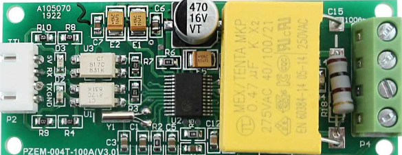
The PZEM-004T is a digital power meter designed for monitoring and measuring key electrical parameters in AC circuits. It provides real-time data on voltage, current, power, energy consumption, and frequency. This module communicates via UART (Universal Asynchronous Receiver-Transmitter), making it easy to integrate with microcontrollers such as the Arduino UNO.
Explore Projects Built with pzem-004t
 Open Project in Cirkit Designer
 Open Project in Cirkit Designer
 Open Project in Cirkit Designer
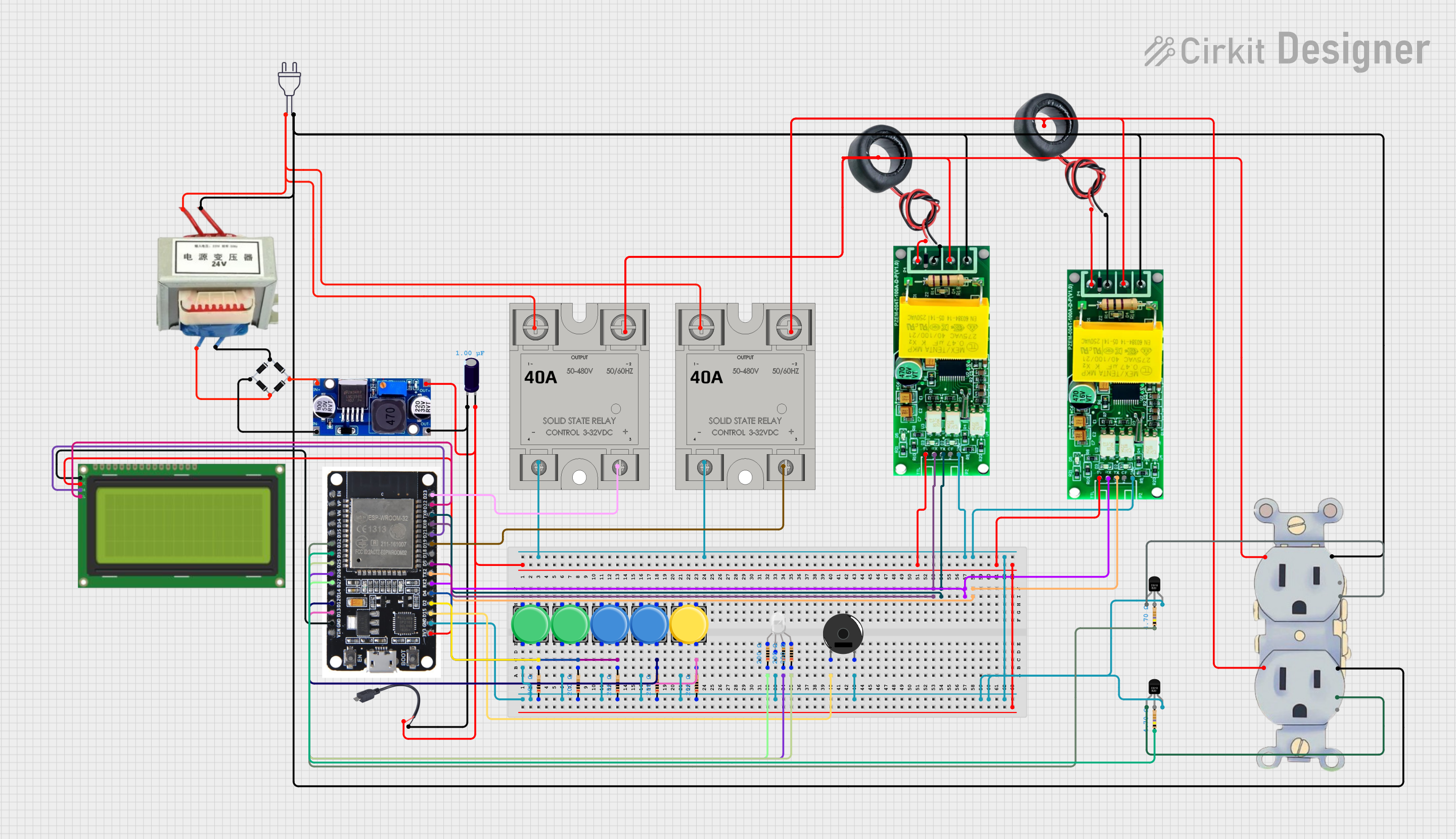 Open Project in Cirkit Designer
Explore Projects Built with pzem-004t
Open Project in Cirkit DesignerOpen Project in Cirkit DesignerOpen Project in Cirkit DesignerOpen Project in Cirkit DesignerCommon Applications and Use Cases
- Home energy monitoring systems
- Industrial power management
- Smart IoT-based energy solutions
- Electrical load analysis
- Renewable energy systems (e.g., solar or wind power monitoring)
Technical Specifications
The following table outlines the key technical details of the PZEM-004T module:
| Parameter | Value |
|---|---|
| Voltage Measurement | 80V - 260V AC |
| Current Measurement | 0A - 100A (with external current transformer) |
| Power Measurement | 0W - 22kW |
| Energy Measurement | 0Wh - 9999kWh |
| Frequency Measurement | 45Hz - 65Hz |
| Communication Protocol | UART (9600 baud rate) |
| Power Supply | 5V DC |
| Accuracy | ±0.5% |
Pin Configuration and Descriptions
The PZEM-004T module has the following pinout:
| Pin Name | Description |
|---|---|
| VCC | Power supply input (5V DC). |
| GND | Ground connection. |
| TX | UART Transmit pin (connects to RX of the microcontroller). |
| RX | UART Receive pin (connects to TX of the microcontroller). |
| AC Input | Connects to the live and neutral wires of the AC circuit for measurement. |
Note: Ensure proper isolation and safety precautions when connecting the module to AC mains.
Usage Instructions
How to Use the PZEM-004T in a Circuit
- Power the Module: Connect the VCC and GND pins of the PZEM-004T to a 5V DC power source.
- Connect UART Pins:
- Connect the TX pin of the PZEM-004T to the RX pin of the Arduino UNO.
- Connect the RX pin of the PZEM-004T to the TX pin of the Arduino UNO.
- AC Input Connection:
- Connect the live and neutral wires of the AC circuit to the module's AC input terminals.
- Use the included current transformer (CT) to measure current by clamping it around the live wire.
- Load the Arduino Code: Use the provided Arduino code to read data from the PZEM-004T.
Important Considerations and Best Practices
- Safety First: The PZEM-004T is connected to high-voltage AC circuits. Ensure proper insulation and avoid direct contact with live wires.
- Current Transformer Placement: The CT should only clamp around the live wire, not both live and neutral wires.
- Baud Rate: The module communicates at a fixed baud rate of 9600. Ensure your microcontroller is configured accordingly.
- Power Supply: Use a stable 5V DC power source to avoid communication errors or inaccurate readings.
Example Arduino Code
Below is an example Arduino sketch to interface the PZEM-004T with an Arduino UNO:
#include <SoftwareSerial.h>

// Define RX and TX pins for SoftwareSerial
SoftwareSerial pzemSerial(10, 11); // RX = Pin 10, TX = Pin 11

// PZEM-004T communication commands
byte readCommand[] = {0xB0, 0xC0, 0xA8, 0x01, 0x01, 0x00, 0x1A};

// Function to send a command to the PZEM-004T
void sendCommand(byte *command, int length) {
  for (int i = 0; i < length; i++) {
    pzemSerial.write(command[i]);
  }
}

void setup() {
  Serial.begin(9600);          // Initialize Serial Monitor
  pzemSerial.begin(9600);      // Initialize SoftwareSerial for PZEM-004T
  delay(100);                  // Allow time for initialization
}

void loop() {
  sendCommand(readCommand, sizeof(readCommand)); // Send read command
  delay(100);                                    // Wait for response

  // Check if data is available from the PZEM-004T
  if (pzemSerial.available()) {
    Serial.println("Data received:");
    while (pzemSerial.available()) {
      byte data = pzemSerial.read();
      Serial.print(data, HEX); // Print data in hexadecimal format
      Serial.print(" ");
    }
    Serial.println();
  } else {
    Serial.println("No data received.");
  }

  delay(1000); // Wait 1 second before the next read
}
Note: This code demonstrates basic communication with the PZEM-004T. For advanced functionality, consider using a dedicated library such as the
PZEM004Tlibrary available in the Arduino IDE Library Manager.
Troubleshooting and FAQs
Common Issues and Solutions
| Issue | Possible Cause | Solution |
|---|---|---|
| No data received from the module | Incorrect UART connections or baud rate mismatch | Verify TX and RX connections and ensure the baud rate is set to 9600. |
| Inaccurate readings | Improper current transformer placement | Ensure the CT is clamped around the live wire only. |
| Module not powering on | Insufficient or unstable power supply | Use a stable 5V DC power source. |
| Communication errors | Electrical noise or long UART cable | Use shorter cables and ensure proper grounding. |
FAQs
Can the PZEM-004T measure DC circuits?
- No, the PZEM-004T is designed specifically for AC circuits.
What is the maximum current the module can measure?
- The module can measure up to 100A using the included current transformer.
Can I use multiple PZEM-004T modules with one Arduino?
- Yes, but you will need to assign unique addresses to each module and use a multiplexer or additional UART ports.
Is the module safe to use with high-voltage circuits?
- Yes, but always follow proper safety precautions and ensure adequate insulation.
By following this documentation, you can effectively integrate the PZEM-004T into your energy monitoring projects.