How to Use 2s BMS: Examples, Pinouts, and Specs
2S Battery Management System (BMS) Documentation
1. Introduction
The 2S Battery Management System (BMS) is an essential electronic component designed to manage and protect two series-connected lithium-ion battery cells. It ensures the safe operation of the battery pack by monitoring and controlling key parameters such as charging, discharging, and cell balancing. The BMS prevents overvoltage, undervoltage, overcurrent, and short-circuit conditions, thereby extending the lifespan of the battery and ensuring reliable performance.
Common Applications
- Lithium-ion battery packs for portable electronics
- Electric bicycles and scooters
- Solar energy storage systems
- Uninterruptible Power Supplies (UPS)
- Robotics and IoT devices
- Power banks and backup power systems
2. Technical Specifications
The following table outlines the key technical details of the 2S BMS:
| Parameter | Value |
|---|---|
| Battery Configuration | 2 Series (2S) Lithium-ion Cells |
| Input Voltage Range | 7.4V to 8.4V (nominal) |
| Overcharge Protection | 4.25V ± 0.05V per cell |
| Overdischarge Protection | 2.5V ± 0.05V per cell |
| Overcurrent Protection | 3A to 20A (varies by model) |
| Balancing Current | 30mA to 60mA |
| Operating Temperature | -40°C to +85°C |
| Dimensions | Typically 20mm x 40mm x 3mm |
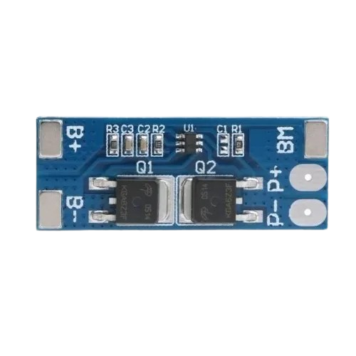
Pin Configuration and Descriptions
| Pin Name | Description |
|---|---|
| B+ | Positive terminal of the battery pack (connect to the positive terminal of Cell 2). |
| B- | Negative terminal of the battery pack (connect to the negative terminal of Cell 1). |
| P+ | Positive terminal of the load/charger (connect to the positive terminal of the circuit). |
| P- | Negative terminal of the load/charger (connect to the negative terminal of the circuit). |
| BM | Midpoint connection between the two cells (connect to the positive terminal of Cell 1). |
3. Usage Instructions
How to Use the 2S BMS in a Circuit
Connect the Battery Pack:
- Connect the B+ pin to the positive terminal of the second cell (Cell 2).
- Connect the BM pin to the positive terminal of the first cell (Cell 1).
- Connect the B- pin to the negative terminal of the first cell (Cell 1).
Connect the Load and Charger:
- Connect the P+ pin to the positive terminal of the load or charger.
- Connect the P- pin to the negative terminal of the load or charger.
Verify Connections:
- Double-check all connections to ensure proper polarity and avoid short circuits.
- Ensure the battery pack voltage is within the supported range of the BMS.
Power On:
- Once all connections are secure, the BMS will automatically manage the battery pack, including charging, discharging, and balancing.
Important Considerations and Best Practices
- Use a battery pack with cells of the same capacity, voltage, and state of charge (SOC).
- Avoid exceeding the maximum current rating of the BMS to prevent damage.
- Ensure proper heat dissipation, especially in high-current applications.
- Do not bypass the BMS for charging or discharging, as this can lead to unsafe conditions.
- Use a charger compatible with the lithium-ion battery chemistry and voltage range.
4. Example Application with Arduino UNO
The 2S BMS can be used in projects involving an Arduino UNO to monitor battery voltage and control loads. Below is an example of how to measure the battery voltage using the Arduino's analog input.
Circuit Diagram
- Connect the P+ and P- terminals of the BMS to the Arduino's power input (Vin and GND).
- Use a voltage divider circuit to step down the battery voltage to a safe range for the Arduino's analog input (0-5V).
Arduino Code Example
// 2S BMS Voltage Monitoring with Arduino UNO
// This code reads the battery voltage using a voltage divider and displays it
// on the Serial Monitor.

const int voltagePin = A0; // Analog pin connected to the voltage divider
const float R1 = 10000.0;  // Resistor R1 value in ohms
const float R2 = 10000.0;  // Resistor R2 value in ohms
const float referenceVoltage = 5.0; // Arduino reference voltage (5V)

void setup() {
  Serial.begin(9600); // Initialize serial communication at 9600 baud
}

void loop() {
  int analogValue = analogRead(voltagePin); // Read the analog input
  float voltage = (analogValue / 1023.0) * referenceVoltage; // Convert to voltage
  float batteryVoltage = voltage * ((R1 + R2) / R2); // Calculate battery voltage

  // Print the battery voltage to the Serial Monitor
  Serial.print("Battery Voltage: ");
  Serial.print(batteryVoltage);
  Serial.println(" V");

  delay(1000); // Wait for 1 second before the next reading
}
Notes:
- Adjust the resistor values (R1 and R2) in the voltage divider to match your circuit.
- Ensure the voltage divider output does not exceed 5V to avoid damaging the Arduino.
5. Troubleshooting and FAQs
Common Issues and Solutions
| Issue | Possible Cause | Solution |
|---|---|---|
| BMS not balancing cells | Cells have a large voltage difference | Pre-charge cells to similar voltages before connecting to the BMS. |
| Overcurrent protection triggers often | Load exceeds the BMS current rating | Use a BMS with a higher current rating or reduce the load current. |
| Battery pack not charging | Incorrect wiring or faulty charger | Verify connections and ensure the charger is compatible with the BMS. |
| BMS overheating | High current or poor heat dissipation | Ensure proper ventilation or use a heatsink if necessary. |
| No output from P+ and P- terminals | Overdischarge protection activated | Recharge the battery pack to reset the BMS. |
FAQs
Can I use the 2S BMS with other battery chemistries?
- No, the 2S BMS is specifically designed for lithium-ion batteries. Using it with other chemistries may result in improper operation or damage.
What happens if I connect the cells in the wrong order?
- Incorrect wiring can damage the BMS. Always follow the pin configuration and double-check connections before powering on.
Can I use the BMS for a 3S or 4S battery pack?
- No, the 2S BMS is designed for two series-connected cells. For 3S or 4S packs, use a BMS designed for the appropriate configuration.
How do I know if the BMS is balancing the cells?
- During balancing, the BMS will draw a small current from the higher-voltage cell(s). You can measure the cell voltages to confirm balancing activity.
This documentation provides a comprehensive guide to understanding, using, and troubleshooting the 2S Battery Management System (BMS). For further assistance, consult the manufacturer's datasheet or contact technical support.
Explore Projects Built with 2s BMS


Explore Projects Built with 2s BMS