
How to Use I2C HUB: Examples, Pinouts, and Specs
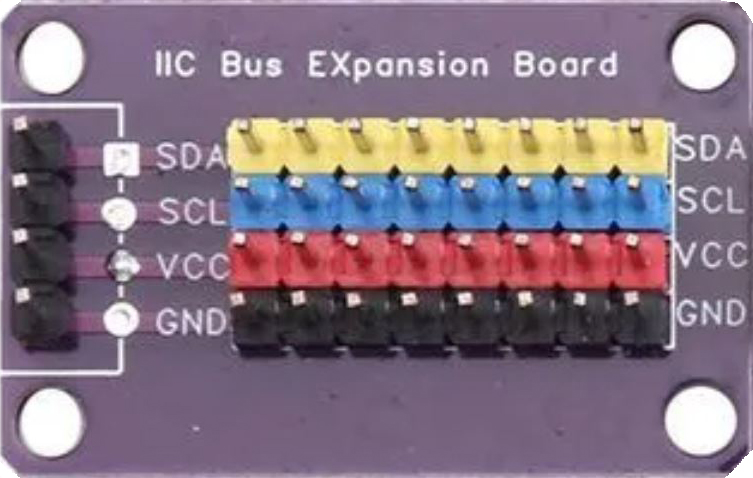
 Design with I2C HUB in Cirkit Designer
Introduction
An I2C HUB is a device that facilitates the connection of multiple I2C devices to a single I2C bus. It acts as a signal distributor, enabling communication between the master controller (e.g., a microcontroller) and multiple slave devices. The I2C HUB ensures proper signal routing and data flow management, making it an essential component in complex I2C-based systems.
Explore Projects Built with I2C HUB
 Open Project in Cirkit Designer
 Open Project in Cirkit Designer
 Open Project in Cirkit Designer
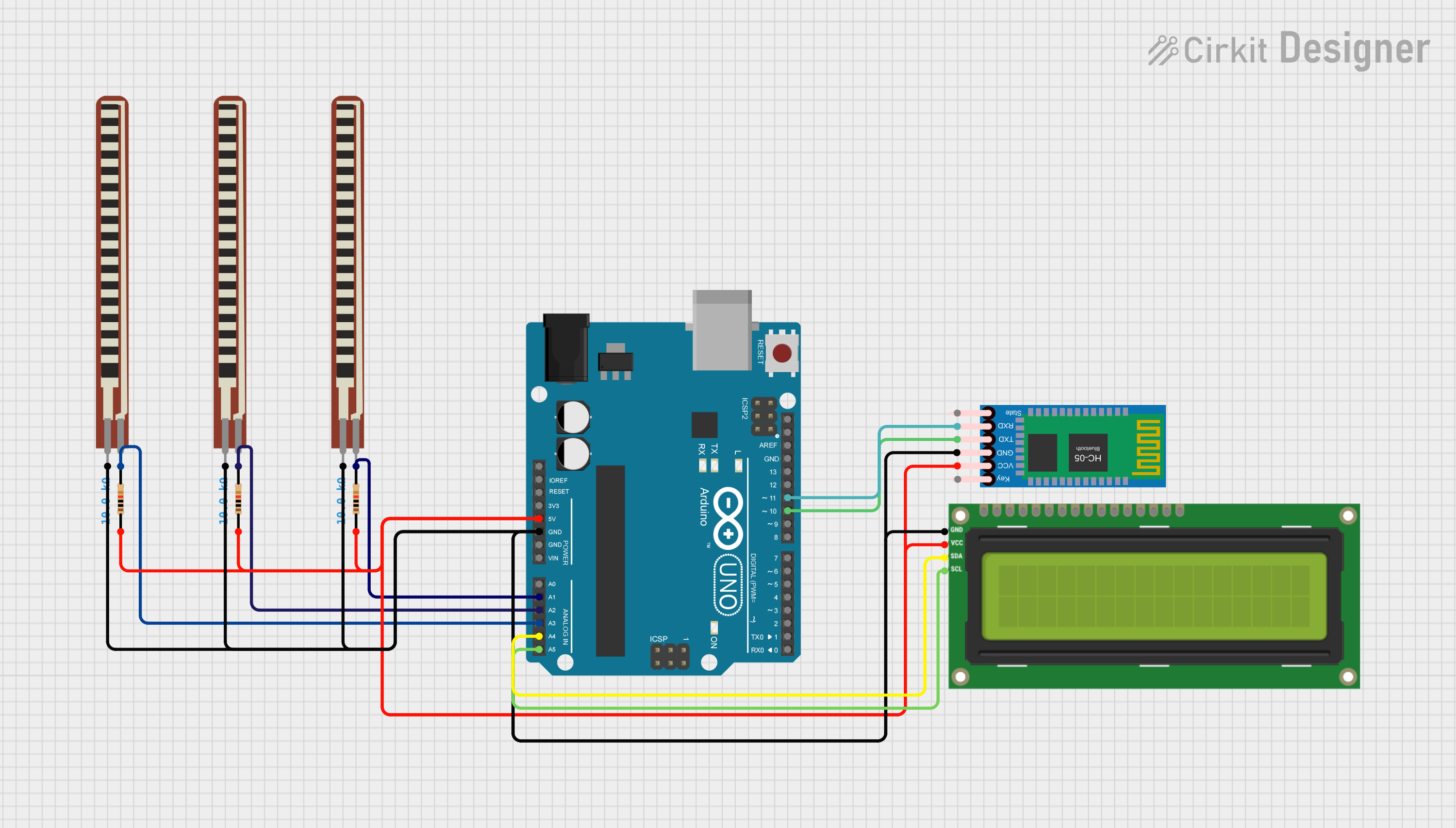 Open Project in Cirkit Designer
Explore Projects Built with I2C HUB
Open Project in Cirkit DesignerOpen Project in Cirkit DesignerOpen Project in Cirkit DesignerOpen Project in Cirkit DesignerCommon Applications and Use Cases
- Expanding the number of I2C devices connected to a single microcontroller.
- Managing communication in systems with multiple sensors, displays, or actuators.
- Prototyping and testing I2C devices in development environments.
- Industrial automation systems requiring multiple I2C peripherals.
- Robotics and IoT applications with limited I2C bus lines.
Technical Specifications
Below are the general technical specifications for a typical I2C HUB. Note that specific values may vary depending on the manufacturer and model.
Key Technical Details
- Operating Voltage: 3.3V to 5V
- I2C Bus Speed: Supports standard (100 kHz), fast (400 kHz), and high-speed (up to 1 MHz) modes
- Number of Ports: Typically 4 to 8 I2C output ports
- Signal Isolation: Optional, depending on the model
- Pull-Up Resistors: Integrated or external (configurable)
- Operating Temperature: -40°C to 85°C (typical)
Pin Configuration and Descriptions
The pin configuration of an I2C HUB may vary, but a typical 6-pin configuration is shown below:
| Pin Name | Description |
|---|---|
| VCC | Power supply input (3.3V or 5V, depending on the HUB model). |
| GND | Ground connection. |
| SDA_IN | Serial Data Line input from the I2C master. |
| SCL_IN | Serial Clock Line input from the I2C master. |
| SDA_OUTx | Serial Data Line output to the I2C slave devices (x = 1, 2, 3, ...). |
| SCL_OUTx | Serial Clock Line output to the I2C slave devices (x = 1, 2, 3, ...). |
Usage Instructions
How to Use the I2C HUB in a Circuit
- Power the HUB: Connect the VCC pin to a 3.3V or 5V power source and the GND pin to ground.
- Connect the Master: Attach the SDA_IN and SCL_IN pins to the corresponding SDA and SCL pins of the I2C master (e.g., a microcontroller or Arduino).
- Connect the Slaves: Connect the SDA_OUTx and SCL_OUTx pins to the SDA and SCL pins of the I2C slave devices.
- Pull-Up Resistors: Ensure that appropriate pull-up resistors are present on the SDA and SCL lines. Some I2C HUBs have integrated pull-ups, while others require external resistors.
- Address Configuration: Verify that each I2C slave device has a unique address to avoid conflicts on the bus.
Important Considerations and Best Practices
- Bus Speed: Ensure that all connected devices support the same I2C bus speed.
- Signal Integrity: For long cables or high-speed communication, consider using an I2C HUB with signal buffering or isolation.
- Power Supply: Verify that the power supply voltage matches the requirements of the I2C HUB and connected devices.
- Address Conflicts: Use address translation or multiplexing if multiple devices share the same I2C address.
Example: Using an I2C HUB with Arduino UNO
Below is an example of connecting an I2C HUB to an Arduino UNO and reading data from two I2C sensors.
Circuit Diagram
- Connect the I2C HUB's VCC and GND to the Arduino's 5V and GND pins.
- Connect the HUB's SDA_IN and SCL_IN to the Arduino's A4 (SDA) and A5 (SCL) pins.
- Connect two I2C sensors to the HUB's SDA_OUT1/SCL_OUT1 and SDA_OUT2/SCL_OUT2.
Arduino Code
#include <Wire.h>

// Define I2C addresses for the two sensors
#define SENSOR1_ADDR 0x40  // Replace with the actual address of sensor 1
#define SENSOR2_ADDR 0x41  // Replace with the actual address of sensor 2

void setup() {
  Wire.begin();  // Initialize the I2C bus
  Serial.begin(9600);  // Start serial communication for debugging
}

void loop() {
  // Read data from sensor 1
  Wire.beginTransmission(SENSOR1_ADDR);
  Wire.write(0x00);  // Replace with the register address to read from
  Wire.endTransmission();
  Wire.requestFrom(SENSOR1_ADDR, 2);  // Request 2 bytes of data
  if (Wire.available() == 2) {
    int data1 = Wire.read() << 8 | Wire.read();  // Combine two bytes
    Serial.print("Sensor 1 Data: ");
    Serial.println(data1);
  }

  // Read data from sensor 2
  Wire.beginTransmission(SENSOR2_ADDR);
  Wire.write(0x00);  // Replace with the register address to read from
  Wire.endTransmission();
  Wire.requestFrom(SENSOR2_ADDR, 2);  // Request 2 bytes of data
  if (Wire.available() == 2) {
    int data2 = Wire.read() << 8 | Wire.read();  // Combine two bytes
    Serial.print("Sensor 2 Data: ");
    Serial.println(data2);
  }

  delay(1000);  // Wait 1 second before the next loop
}
Troubleshooting and FAQs
Common Issues and Solutions
No Communication with Devices
- Cause: Incorrect wiring or missing pull-up resistors.
- Solution: Double-check all connections and ensure pull-up resistors are present.
Address Conflicts
- Cause: Two or more devices share the same I2C address.
- Solution: Use devices with configurable addresses or an address translator.
Data Corruption
- Cause: Excessive bus length or noise.
- Solution: Use shielded cables or an I2C HUB with signal buffering.
Devices Not Detected
- Cause: Incorrect power supply voltage.
- Solution: Verify that the power supply matches the requirements of the devices.
FAQs
Q: Can I connect devices with different voltage levels to the same I2C HUB?
A: Only if the HUB supports voltage level translation. Otherwise, use level shifters.Q: How many devices can I connect to an I2C HUB?
A: This depends on the HUB model and the total bus capacitance. Most HUBs support 4 to 8 devices.Q: Do I need external pull-up resistors if the HUB has integrated ones?
A: No, but ensure the integrated resistors are suitable for your application.