How to Use megamoto: Examples, Pinouts, and Specs
Introduction
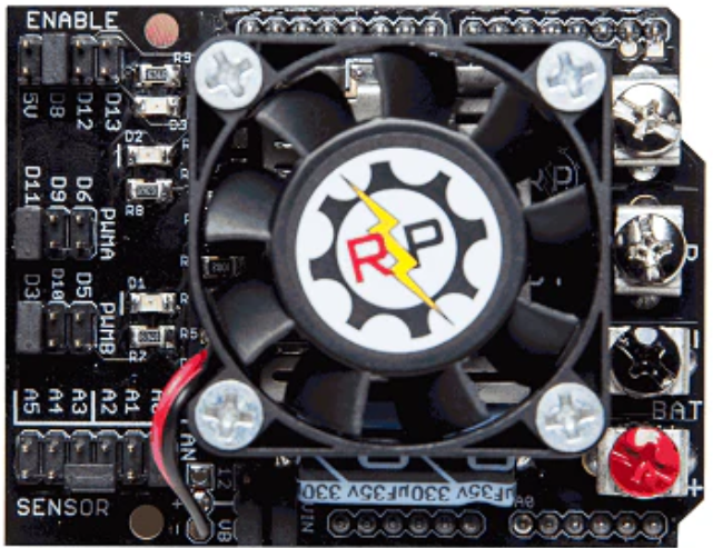
The MegaMoto is a high-performance motor driver designed for controlling DC motors and stepper motors in robotics and automation applications. It provides advanced features such as speed control, direction control, and current limiting, making it an ideal choice for projects requiring precise motor control. The MegaMoto is compatible with microcontrollers like Arduino, enabling seamless integration into a wide range of applications.
Explore Projects Built with megamoto
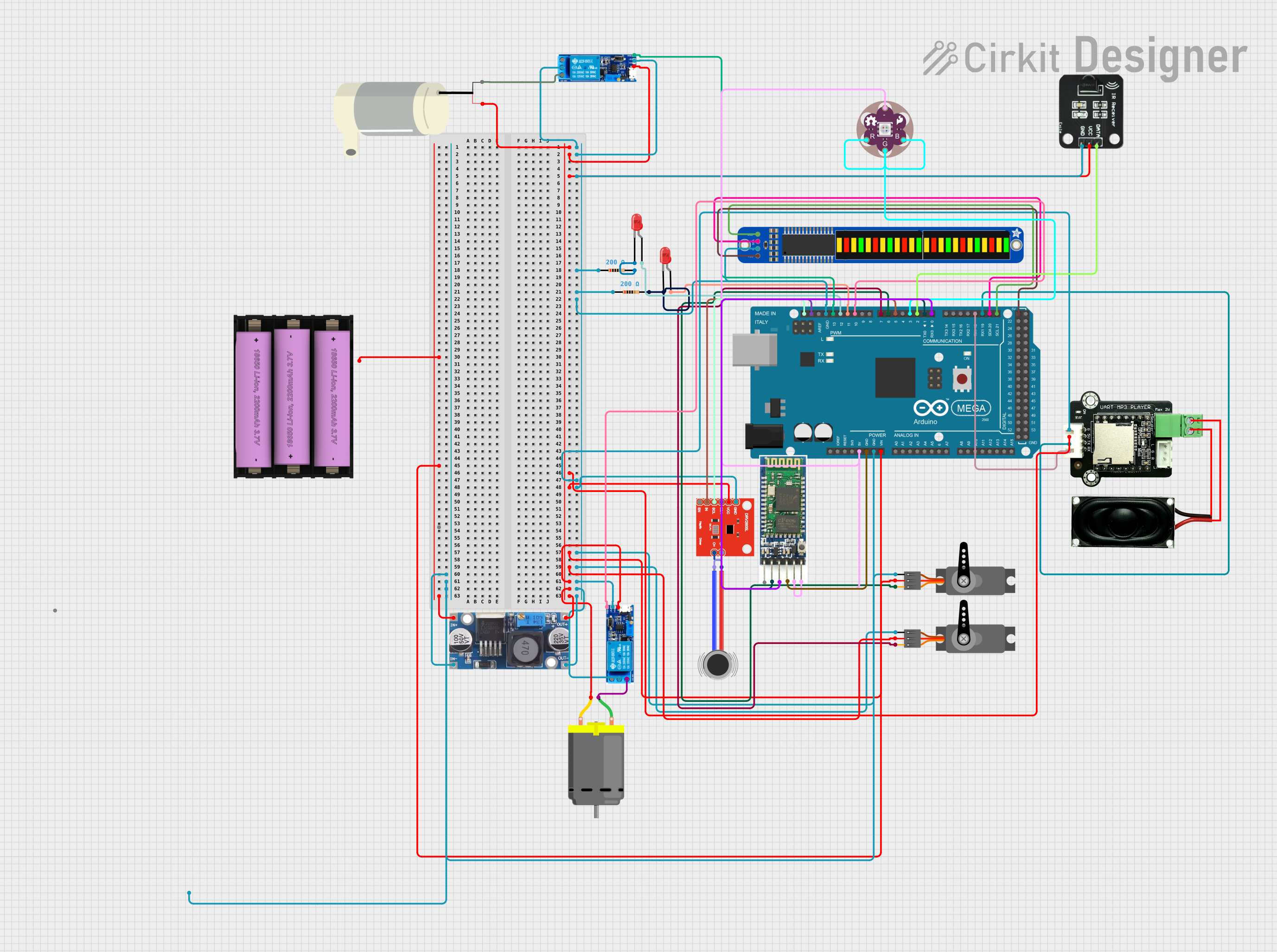

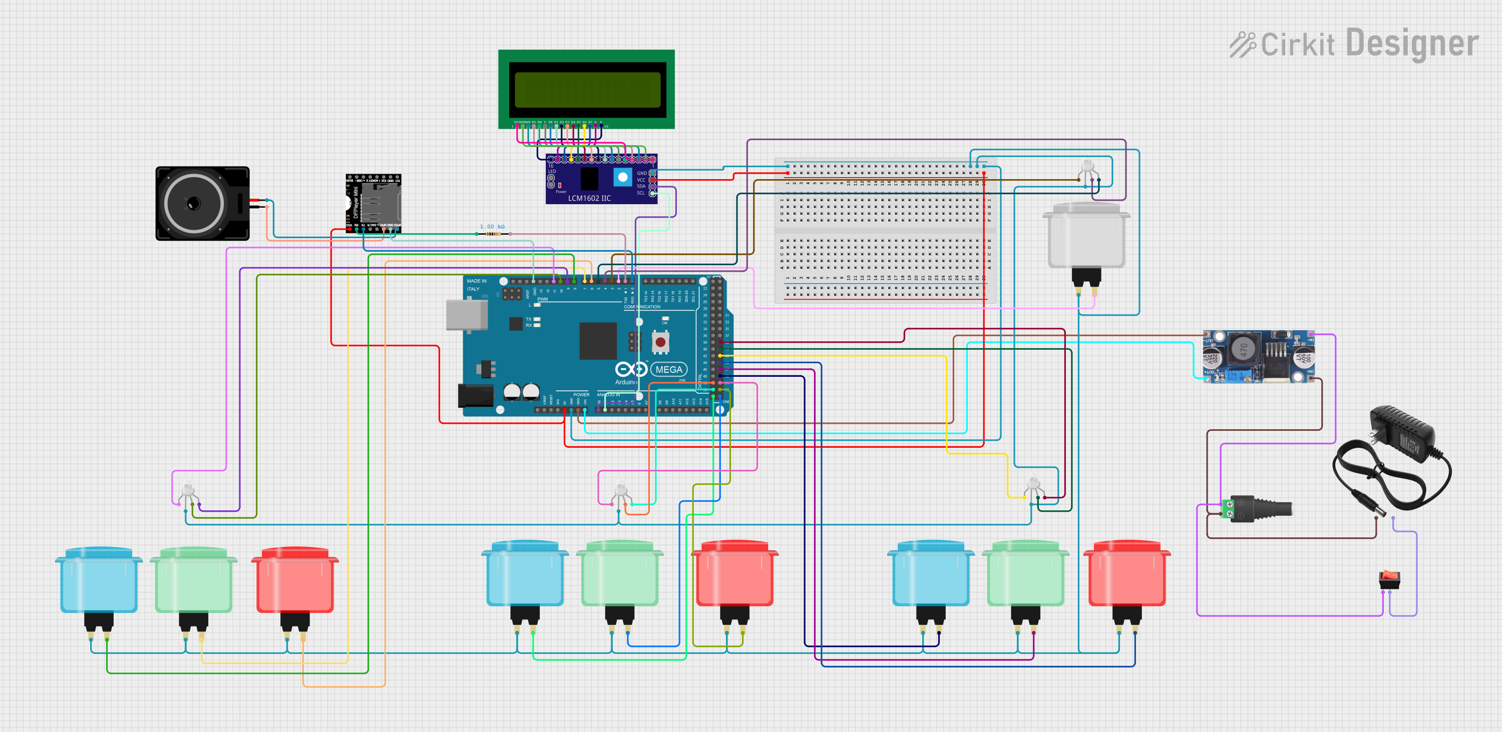
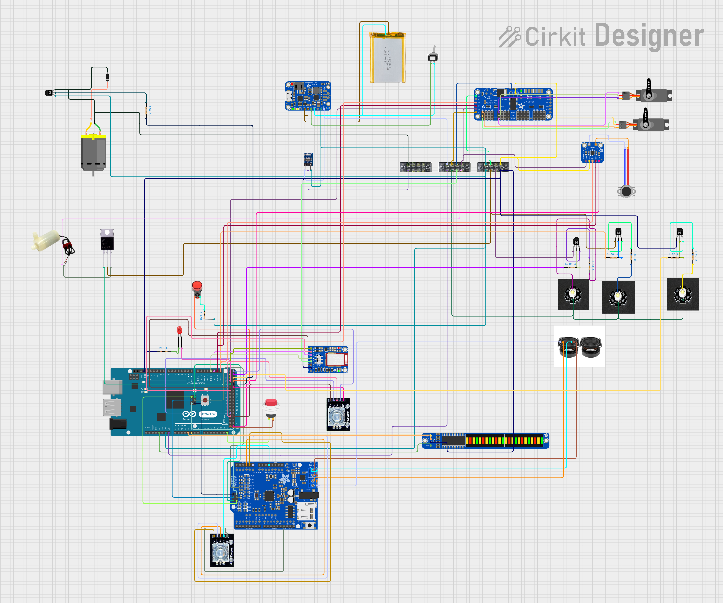
Explore Projects Built with megamoto
Common Applications and Use Cases
- Robotics and automation systems
- Electric vehicles and motorized platforms
- Conveyor belts and industrial machinery
- CNC machines and 3D printers
- Hobbyist projects involving DC or stepper motors
Technical Specifications
The MegaMoto motor driver is built to handle high-power motors while maintaining efficiency and reliability. Below are its key technical specifications:
| Parameter | Value |
|---|---|
| Operating Voltage | 6V to 28V |
| Continuous Current | Up to 13A per channel |
| Peak Current | 30A per channel (for short bursts) |
| PWM Frequency | Up to 20 kHz |
| Logic Voltage | 3.3V or 5V (compatible with Arduino) |
| Control Interface | PWM and Direction pins |
| Thermal Protection | Built-in thermal shutdown |
| Dimensions | 68mm x 53mm x 15mm |
Pin Configuration and Descriptions
The MegaMoto has a straightforward pin layout for easy integration. Below is the pin configuration:
| Pin Name | Type | Description |
|---|---|---|
| VIN | Power Input | Motor power supply (6V to 28V). |
| GND | Power Ground | Common ground for power and logic. |
| PWM_A | Input | PWM signal for motor channel A. |
| DIR_A | Input | Direction control for motor channel A. |
| PWM_B | Input | PWM signal for motor channel B. |
| DIR_B | Input | Direction control for motor channel B. |
| EN | Input | Enable pin to activate the motor driver. |
| CS_A | Output | Current sense output for motor channel A. |
| CS_B | Output | Current sense output for motor channel B. |
Usage Instructions
The MegaMoto motor driver is easy to use with microcontrollers like Arduino. Follow these steps to integrate it into your project:
Step 1: Wiring the MegaMoto
- Connect the VIN pin to the motor power supply (6V to 28V).
- Connect the GND pin to the ground of the power supply and the microcontroller.
- Connect the PWM_A and DIR_A pins to the corresponding PWM and digital output pins on the microcontroller for motor channel A.
- Similarly, connect the PWM_B and DIR_B pins for motor channel B.
- Optionally, connect the CS_A and CS_B pins to analog input pins on the microcontroller to monitor motor current.
- Connect the EN pin to a digital output pin on the microcontroller to enable or disable the motor driver.
Step 2: Programming the Arduino
Below is an example Arduino sketch to control two DC motors using the MegaMoto:
// Define pins for motor control
#define PWM_A 3  // PWM pin for motor channel A
#define DIR_A 4  // Direction pin for motor channel A
#define PWM_B 5  // PWM pin for motor channel B
#define DIR_B 6  // Direction pin for motor channel B
#define EN 7     // Enable pin for the MegaMoto

void setup() {
  // Set motor control pins as outputs
  pinMode(PWM_A, OUTPUT);
  pinMode(DIR_A, OUTPUT);
  pinMode(PWM_B, OUTPUT);
  pinMode(DIR_B, OUTPUT);
  pinMode(EN, OUTPUT);

  // Enable the MegaMoto driver
  digitalWrite(EN, HIGH);
}

void loop() {
  // Example: Rotate motor A forward at 50% speed
  digitalWrite(DIR_A, HIGH);  // Set direction forward
  analogWrite(PWM_A, 128);    // Set speed (0-255)

  // Example: Rotate motor B backward at 75% speed
  digitalWrite(DIR_B, LOW);   // Set direction backward
  analogWrite(PWM_B, 192);    // Set speed (0-255)

  delay(5000);  // Run motors for 5 seconds

  // Stop both motors
  analogWrite(PWM_A, 0);
  analogWrite(PWM_B, 0);

  delay(2000);  // Wait for 2 seconds before repeating
}
Important Considerations and Best Practices
- Ensure the motor power supply voltage is within the specified range (6V to 28V).
- Use appropriate heat sinks or cooling mechanisms if operating at high currents for extended periods.
- Avoid reversing the polarity of the power supply to prevent damage to the MegaMoto.
- Use fuses or circuit breakers to protect the motor driver and connected components.
- Monitor the current sense outputs (CS_A and CS_B) to detect overcurrent conditions.
Troubleshooting and FAQs
Common Issues and Solutions
Motor does not spin:
- Verify that the EN pin is set to HIGH to enable the driver.
- Check the wiring of the PWM and DIR pins to ensure proper connections.
- Ensure the motor power supply is connected and within the specified voltage range.
Motor spins in the wrong direction:
- Reverse the logic level on the DIR pin for the corresponding motor channel.
Driver overheats:
- Check for excessive current draw from the motors. Use motors within the driver's current rating.
- Add a heat sink or active cooling to the MegaMoto.
Arduino resets when motors start:
- Ensure the motor power supply and Arduino share a common ground.
- Use a separate power supply for the motors to avoid voltage drops affecting the Arduino.
FAQs
Q: Can the MegaMoto control stepper motors?
A: Yes, the MegaMoto can control stepper motors by driving each coil with one motor channel. However, you will need to implement stepper motor control logic in your code.
Q: Is the MegaMoto compatible with 3.3V logic?
A: Yes, the MegaMoto is compatible with both 3.3V and 5V logic levels, making it suitable for a wide range of microcontrollers.
Q: How do I monitor motor current?
A: Connect the CS_A and CS_B pins to analog input pins on your microcontroller. The voltage on these pins is proportional to the motor current.
By following this documentation, you can effectively integrate the MegaMoto motor driver into your projects and achieve precise motor control.