How to Use XL6009: Examples, Pinouts, and Specs
Introduction
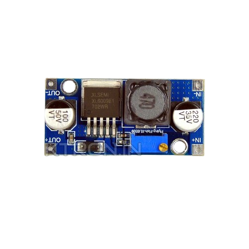
The XL6009 is a high-performance, step-up (boost) DC-DC converter designed to increase a lower input voltage to a higher, stable output voltage. It is based on a high-efficiency switching regulator and is capable of delivering a maximum output current of approximately 3A. The XL6009 is widely used in applications requiring voltage regulation, such as battery-powered devices, LED drivers, solar power systems, and portable electronics.
Explore Projects Built with XL6009


Explore Projects Built with XL6009
Common Applications and Use Cases
- Powering devices requiring a higher voltage than the input source (e.g., 5V to 12V conversion)
- LED lighting systems
- Solar panel voltage regulation
- Battery-powered devices
- DIY electronics projects
- Arduino and microcontroller-based systems
Technical Specifications
The XL6009 is a versatile and robust component with the following key specifications:
| Parameter | Value |
|---|---|
| Input Voltage Range | 3V to 32V |
| Output Voltage Range | 5V to 35V (adjustable via potentiometer) |
| Maximum Output Current | 3A (with proper heat dissipation) |
| Switching Frequency | 400 kHz |
| Efficiency | Up to 94% |
| Operating Temperature | -40°C to +85°C |
| Dimensions (module) | ~43mm x 21mm x 14mm |
Pin Configuration and Descriptions
The XL6009 is typically available as a module with the following pinout:
| Pin Name | Description |
|---|---|
| VIN | Input voltage (3V to 32V). Connect to the power source. |
| GND | Ground connection. Common ground for input and output. |
| VOUT | Output voltage (5V to 35V). Connect to the load. |
| ADJ | Adjustable pin. Used to set the output voltage via the |
| onboard potentiometer. |
Usage Instructions
How to Use the XL6009 in a Circuit
Connect the Input Voltage (VIN):
- Attach the positive terminal of your power source to the
VINpin. - Connect the negative terminal of your power source to the
GNDpin.
- Attach the positive terminal of your power source to the
Set the Desired Output Voltage:
- Use the onboard potentiometer to adjust the output voltage.
- Turn the potentiometer clockwise to increase the output voltage or counterclockwise to decrease it.
- Use a multimeter to measure the output voltage at the
VOUTpin while adjusting.
Connect the Load:
- Attach the positive terminal of your load to the
VOUTpin. - Connect the negative terminal of your load to the
GNDpin.
- Attach the positive terminal of your load to the
Power On the Circuit:
- Ensure all connections are secure and within the specified voltage/current limits.
- Turn on the power source and verify the output voltage.
Important Considerations and Best Practices
- Heat Dissipation: The XL6009 can handle up to 3A, but proper heat dissipation (e.g., a heatsink) is required for high current loads.
- Input Voltage: Ensure the input voltage is within the specified range (3V to 32V). Exceeding this range may damage the module.
- Output Voltage Adjustment: Always measure the output voltage with a multimeter when adjusting the potentiometer to avoid overvoltage damage to your load.
- Capacitor Selection: Use appropriate input and output capacitors to reduce voltage ripple and improve stability.
- Arduino Compatibility: The XL6009 can be used to power Arduino boards by setting the output voltage to 5V or 9V, depending on the board's requirements.
Example: Using XL6009 with Arduino UNO
To power an Arduino UNO using the XL6009, follow these steps:
- Set the XL6009 output voltage to 9V using the potentiometer.
- Connect the
VOUTpin to the Arduino's VIN pin. - Connect the
GNDpin to the Arduino's GND pin.
Here is an example Arduino sketch to blink an LED while powered by the XL6009:
// Simple LED Blink Example
// This code blinks an LED connected to pin 13 of the Arduino UNO.
// Ensure the XL6009 is set to output 9V to power the Arduino.

void setup() {
  pinMode(13, OUTPUT); // Set pin 13 as an output
}

void loop() {
  digitalWrite(13, HIGH); // Turn the LED on
  delay(1000);            // Wait for 1 second
  digitalWrite(13, LOW);  // Turn the LED off
  delay(1000);            // Wait for 1 second
}
Troubleshooting and FAQs
Common Issues and Solutions
No Output Voltage:
- Cause: Incorrect wiring or insufficient input voltage.
- Solution: Double-check all connections and ensure the input voltage is within the specified range.
Output Voltage is Unstable:
- Cause: Insufficient input/output capacitors or excessive load.
- Solution: Add appropriate capacitors (e.g., 100µF electrolytic) to the input and output.
Overheating:
- Cause: High current load without proper heat dissipation.
- Solution: Attach a heatsink to the XL6009 module or reduce the load current.
Output Voltage Not Adjustable:
- Cause: Faulty potentiometer or incorrect adjustment.
- Solution: Verify the potentiometer is functional and adjust it carefully while monitoring the output voltage.
FAQs
Q: Can the XL6009 step down voltage as well?
A: No, the XL6009 is a step-up (boost) converter and cannot step down voltage. For step-down applications, use a buck converter like the LM2596.
Q: What is the maximum input current for the XL6009?
A: The input current depends on the load and efficiency. For a 3A output at 12V, the input current will be higher due to power conversion losses.
Q: Can I use the XL6009 with a solar panel?
A: Yes, the XL6009 is suitable for solar panel applications. Ensure the input voltage is within the module's range and use capacitors to stabilize the input.
Q: Is the XL6009 safe for sensitive electronics?
A: Yes, but ensure proper voltage adjustment and use capacitors to minimize voltage ripple. Always test the output voltage before connecting sensitive devices.