How to Use Digital Vibration Sensor: Examples, Pinouts, and Specs
Introduction
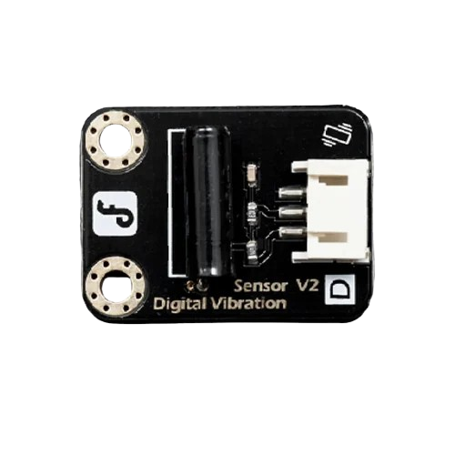
The Gravity Digital Vibration Sensor is a compact and reliable device designed to detect vibrations and convert them into digital signals for further processing. This sensor is ideal for applications requiring motion detection, structural health monitoring, and robotics. Its simple interface and robust design make it suitable for both beginners and advanced users in electronics and IoT projects.
Explore Projects Built with Digital Vibration Sensor
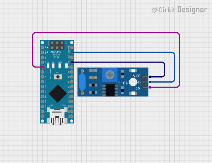
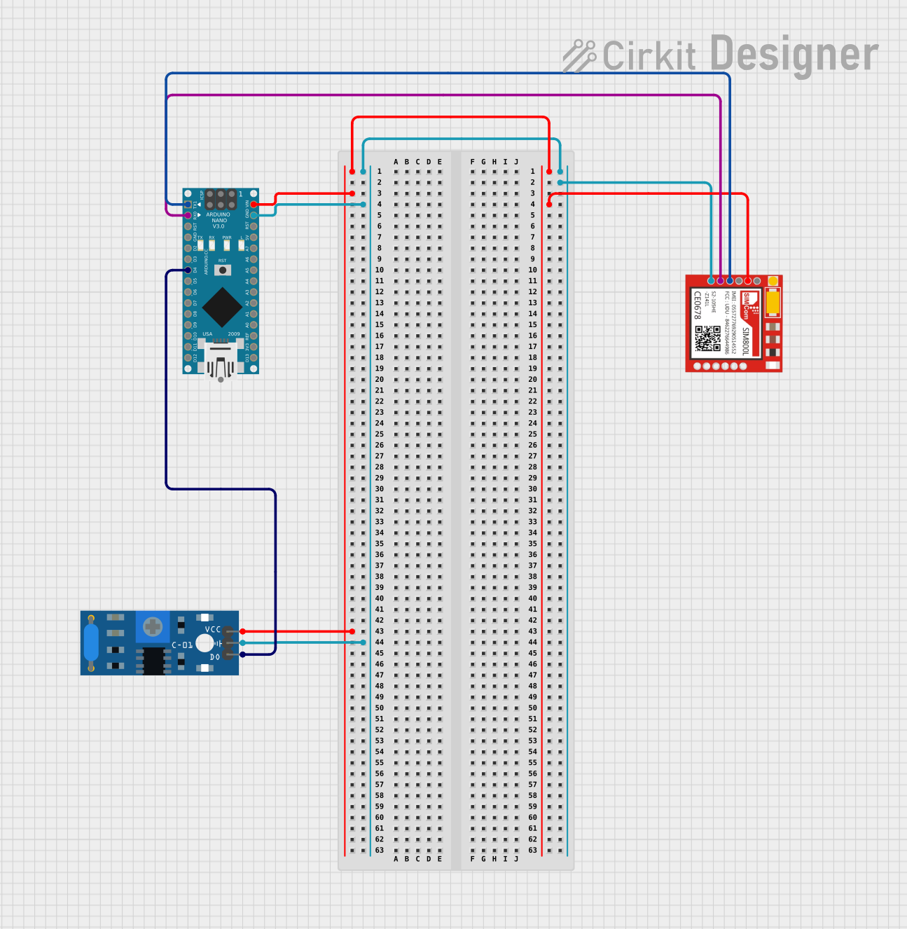

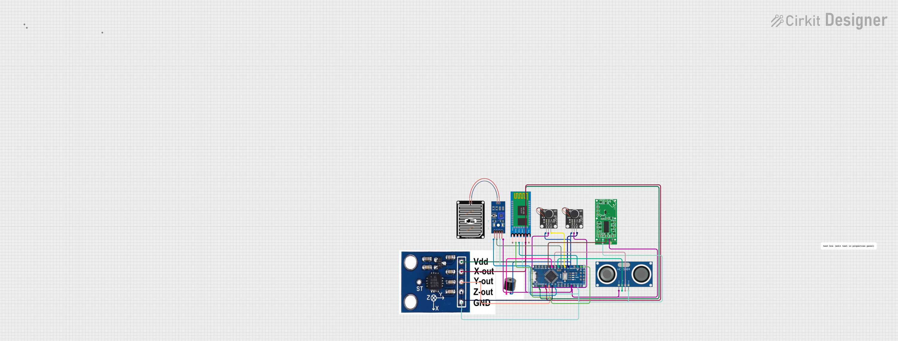
Explore Projects Built with Digital Vibration Sensor
Common Applications
- Motion detection in security systems
- Structural health monitoring in buildings and bridges
- Robotics for detecting environmental vibrations
- Industrial machinery monitoring
- Gaming devices for vibration-based input
Technical Specifications
The following table outlines the key technical details of the Gravity Digital Vibration Sensor:
| Parameter | Specification |
|---|---|
| Operating Voltage | 3.3V to 5V |
| Output Signal | Digital (High/Low) |
| Sensitivity | Adjustable via onboard potentiometer |
| Interface Type | 3-pin interface (Signal, VCC, GND) |
| Dimensions | 30mm x 20mm |
| Weight | 5g |
Pin Configuration and Descriptions
The sensor has a 3-pin interface, as described in the table below:
| Pin | Name | Description |
|---|---|---|
| 1 | Signal | Outputs a digital HIGH (1) when vibration is detected |
| 2 | VCC | Power supply pin (3.3V to 5V) |
| 3 | GND | Ground connection |
Usage Instructions
How to Use the Sensor in a Circuit
Connect the Sensor:
- Connect the
VCCpin to a 3.3V or 5V power source. - Connect the
GNDpin to the ground of your circuit. - Connect the
Signalpin to a digital input pin on your microcontroller (e.g., Arduino).
- Connect the
Adjust Sensitivity:
- Use the onboard potentiometer to adjust the sensitivity of the sensor. Turning the potentiometer clockwise increases sensitivity, while turning it counterclockwise decreases sensitivity.
Read the Output:
- When the sensor detects vibration, the
Signalpin outputs a HIGH signal (1). Otherwise, it remains LOW (0).
- When the sensor detects vibration, the
Important Considerations and Best Practices
- Power Supply: Ensure the sensor operates within the specified voltage range (3.3V to 5V) to avoid damage.
- Debouncing: The sensor may produce multiple signals for a single vibration. Implement software debouncing in your code to filter out false triggers.
- Placement: Mount the sensor securely to avoid false readings caused by loose connections or external noise.
- Environmental Factors: Avoid placing the sensor in environments with excessive electromagnetic interference (EMI) or extreme temperatures.
Example Code for Arduino UNO
Below is an example of how to use the Gravity Digital Vibration Sensor with an Arduino UNO:
// Example code for using the Gravity Digital Vibration Sensor with Arduino UNO

const int sensorPin = 2;  // Connect the Signal pin of the sensor to digital pin 2
const int ledPin = 13;    // Built-in LED on Arduino for visual feedback

void setup() {
  pinMode(sensorPin, INPUT);  // Set the sensor pin as an input
  pinMode(ledPin, OUTPUT);    // Set the LED pin as an output
  Serial.begin(9600);         // Initialize serial communication at 9600 baud
}

void loop() {
  int sensorValue = digitalRead(sensorPin);  // Read the sensor's output

  if (sensorValue == HIGH) {
    // If vibration is detected, turn on the LED and print a message
    digitalWrite(ledPin, HIGH);
    Serial.println("Vibration detected!");
  } else {
    // If no vibration is detected, turn off the LED
    digitalWrite(ledPin, LOW);
  }

  delay(100);  // Add a small delay to stabilize readings
}
Troubleshooting and FAQs
Common Issues and Solutions
Sensor Not Detecting Vibrations:
- Solution: Check the power supply connections and ensure the sensor is receiving 3.3V to 5V. Adjust the sensitivity using the onboard potentiometer.
False Triggers or Noise:
- Solution: Implement software debouncing in your code to filter out noise. Ensure the sensor is securely mounted to avoid false readings caused by loose connections.
No Output Signal:
- Solution: Verify the wiring and ensure the
Signalpin is connected to the correct digital input pin on your microcontroller. Check for any damage to the sensor.
- Solution: Verify the wiring and ensure the
Interference from Nearby Devices:
- Solution: Place the sensor away from sources of electromagnetic interference (e.g., motors, high-frequency devices).
FAQs
Q: Can this sensor detect continuous vibrations?
A: The sensor is designed to detect individual vibration events. For continuous vibrations, you may need to process the output signal in software to analyze patterns.
Q: Is the sensor compatible with 3.3V microcontrollers like ESP32?
A: Yes, the sensor operates within a voltage range of 3.3V to 5V, making it compatible with 3.3V microcontrollers.
Q: How do I increase the detection range?
A: You can increase the sensitivity by adjusting the onboard potentiometer. However, be cautious as higher sensitivity may also increase false triggers.
Q: Can I use this sensor outdoors?
A: The sensor is not waterproof or weatherproof. If used outdoors, ensure it is enclosed in a protective casing to prevent damage from moisture or dust.