How to Use m10q: Examples, Pinouts, and Specs
Introduction
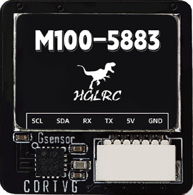
The M10Q is a high-performance N-channel MOSFET manufactured by HGLRC with the part ID GPS. It is designed for efficient switching applications, offering low on-resistance and fast switching speeds. These features make the M10Q ideal for power management, signal amplification, and other high-speed electronic circuits.
Explore Projects Built with m10q
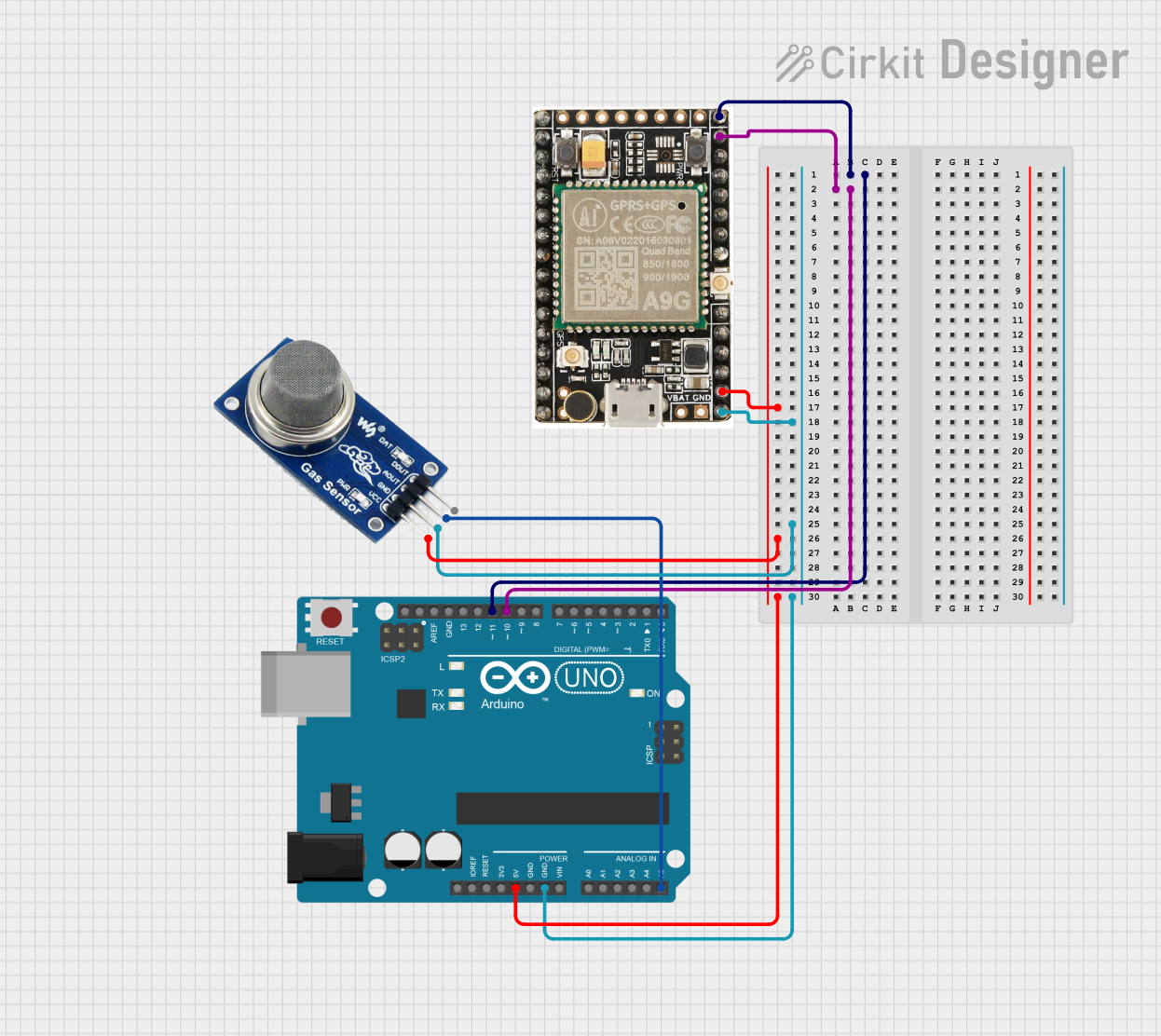

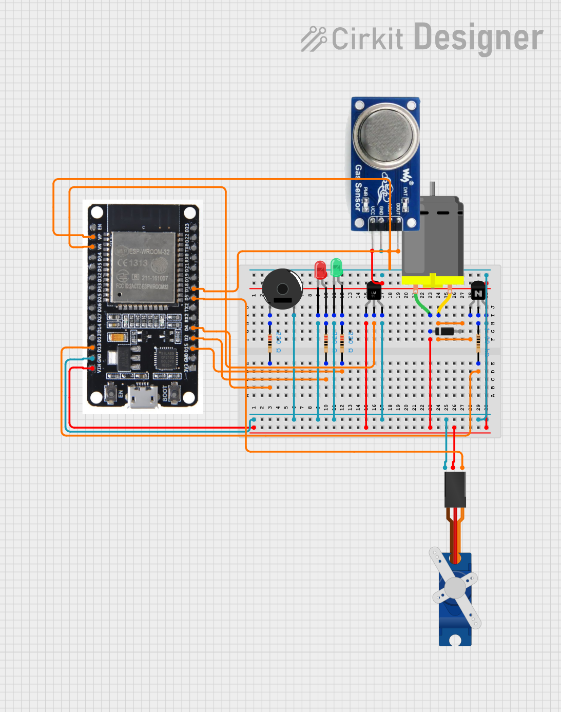
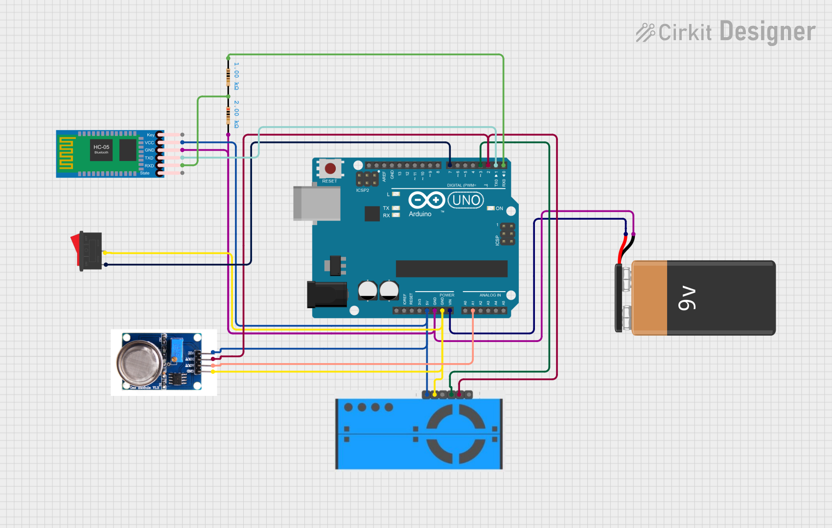
Explore Projects Built with m10q
Common Applications
- DC-DC converters
- Motor drivers
- Power management in portable devices
- Signal amplification in audio and RF circuits
- Switching regulators
Technical Specifications
Key Specifications
| Parameter | Value |
|---|---|
| Type | N-Channel MOSFET |
| Manufacturer | HGLRC |
| Part ID | GPS |
| Maximum Drain-Source Voltage (VDS) | 30V |
| Maximum Gate-Source Voltage (VGS) | ±20V |
| Continuous Drain Current (ID) | 10A |
| Pulsed Drain Current (ID,pulse) | 40A |
| On-Resistance (RDS(on)) | 0.02Ω (at VGS = 10V) |
| Gate Threshold Voltage (VGS(th)) | 1.5V - 2.5V |
| Power Dissipation (PD) | 50W |
| Operating Temperature Range | -55°C to +150°C |
| Package Type | TO-220 |
Pin Configuration
The M10Q MOSFET is typically available in a TO-220 package with three pins. The pin configuration is as follows:
| Pin Number | Name | Description |
|---|---|---|
| 1 | Gate (G) | Controls the MOSFET switching state |
| 2 | Drain (D) | Current flows from drain to source |
| 3 | Source (S) | Connected to ground or load return |
Usage Instructions
Using the M10Q in a Circuit
- Gate Control: Apply a voltage to the Gate (G) to control the MOSFET's switching state. Ensure the gate voltage (VGS) is within the specified range (±20V).
- Load Connection: Connect the load between the Drain (D) and the positive supply voltage. The Source (S) is typically connected to ground.
- Driving the Gate: Use a gate driver circuit or a microcontroller to provide the required gate voltage. For optimal performance, ensure the gate voltage is at least 10V for full enhancement mode.
- Heat Dissipation: Use a heatsink if the MOSFET operates at high currents to prevent overheating.
Example Circuit with Arduino UNO
The M10Q can be used with an Arduino UNO to control a DC motor. Below is an example circuit and code:
Circuit Description
- Connect the Source (S) pin of the M10Q to ground.
- Connect the Drain (D) pin to one terminal of the DC motor.
- Connect the other terminal of the motor to the positive supply voltage (e.g., 12V).
- Connect the Gate (G) pin to a PWM-capable pin on the Arduino (e.g., Pin 9) through a 220Ω resistor.
- Add a flyback diode across the motor terminals to protect the MOSFET from voltage spikes.
Arduino Code
// Example code to control a DC motor using the M10Q MOSFET and Arduino UNO

const int motorPin = 9; // PWM pin connected to the Gate of the M10Q MOSFET

void setup() {
  pinMode(motorPin, OUTPUT); // Set the motor pin as an output
}

void loop() {
  // Gradually increase motor speed
  for (int speed = 0; speed <= 255; speed++) {
    analogWrite(motorPin, speed); // Write PWM signal to the Gate
    delay(10); // Small delay for smooth acceleration
  }

  delay(1000); // Run at full speed for 1 second

  // Gradually decrease motor speed
  for (int speed = 255; speed >= 0; speed--) {
    analogWrite(motorPin, speed); // Write PWM signal to the Gate
    delay(10); // Small delay for smooth deceleration
  }

  delay(1000); // Wait for 1 second before repeating
}
Best Practices
- Use a pull-down resistor (e.g., 10kΩ) on the Gate pin to ensure the MOSFET remains off when no signal is applied.
- Avoid exceeding the maximum voltage and current ratings to prevent damage.
- Use proper decoupling capacitors near the power supply to reduce noise and voltage spikes.
Troubleshooting and FAQs
Common Issues and Solutions
| Issue | Possible Cause | Solution |
|---|---|---|
| MOSFET overheating | Excessive current or insufficient cooling | Use a heatsink or reduce the load current |
| MOSFET not switching on | Insufficient gate voltage | Ensure VGS is at least 10V |
| Motor not running | Incorrect wiring or damaged MOSFET | Verify connections and replace the MOSFET |
| Voltage spikes damaging the MOSFET | Inductive load without flyback diode | Add a flyback diode across the load |
FAQs
Can the M10Q handle AC loads?
- No, the M10Q is designed for DC applications. For AC loads, consider using a TRIAC or IGBT.
What is the maximum PWM frequency for the M10Q?
- The M10Q supports high-speed switching, typically up to 100kHz. However, performance depends on the gate driver and load characteristics.
Do I need a gate driver for the M10Q?
- A gate driver is recommended for high-speed or high-current applications to ensure fast and efficient switching.
Can I use the M10Q with a 3.3V microcontroller?
- The M10Q requires a gate voltage of at least 10V for full enhancement. Use a level shifter or gate driver to interface with a 3.3V microcontroller.
By following this documentation, you can effectively integrate the M10Q MOSFET into your electronic projects for efficient and reliable performance.