How to Use Probe: Examples, Pinouts, and Specs
Introduction
A probe is a versatile tool used to measure electrical signals in a circuit. It is commonly employed in testing, diagnostics, and debugging of electronic systems. Probes are essential for engineers, technicians, and hobbyists to analyze voltage, current, and other electrical parameters in a circuit without permanently altering or damaging the system.
Explore Projects Built with Probe
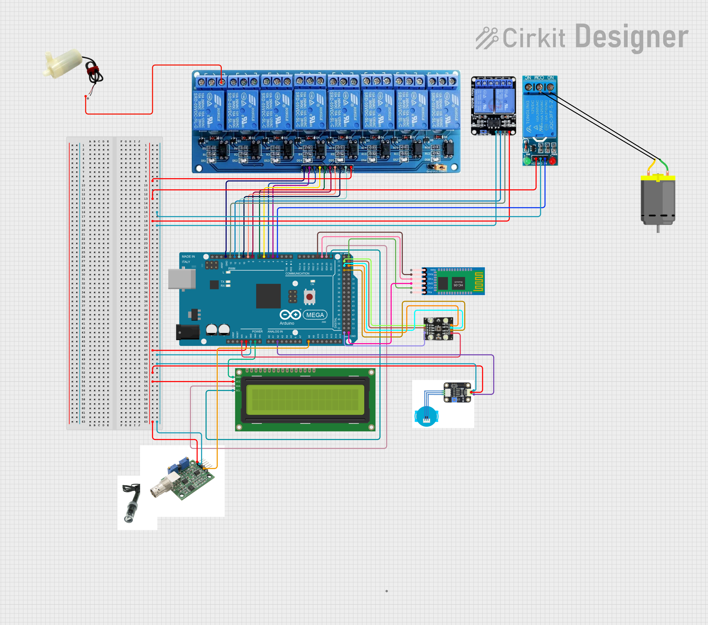
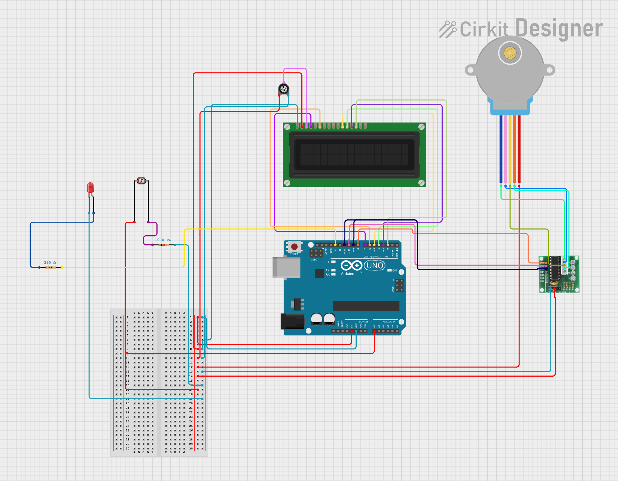
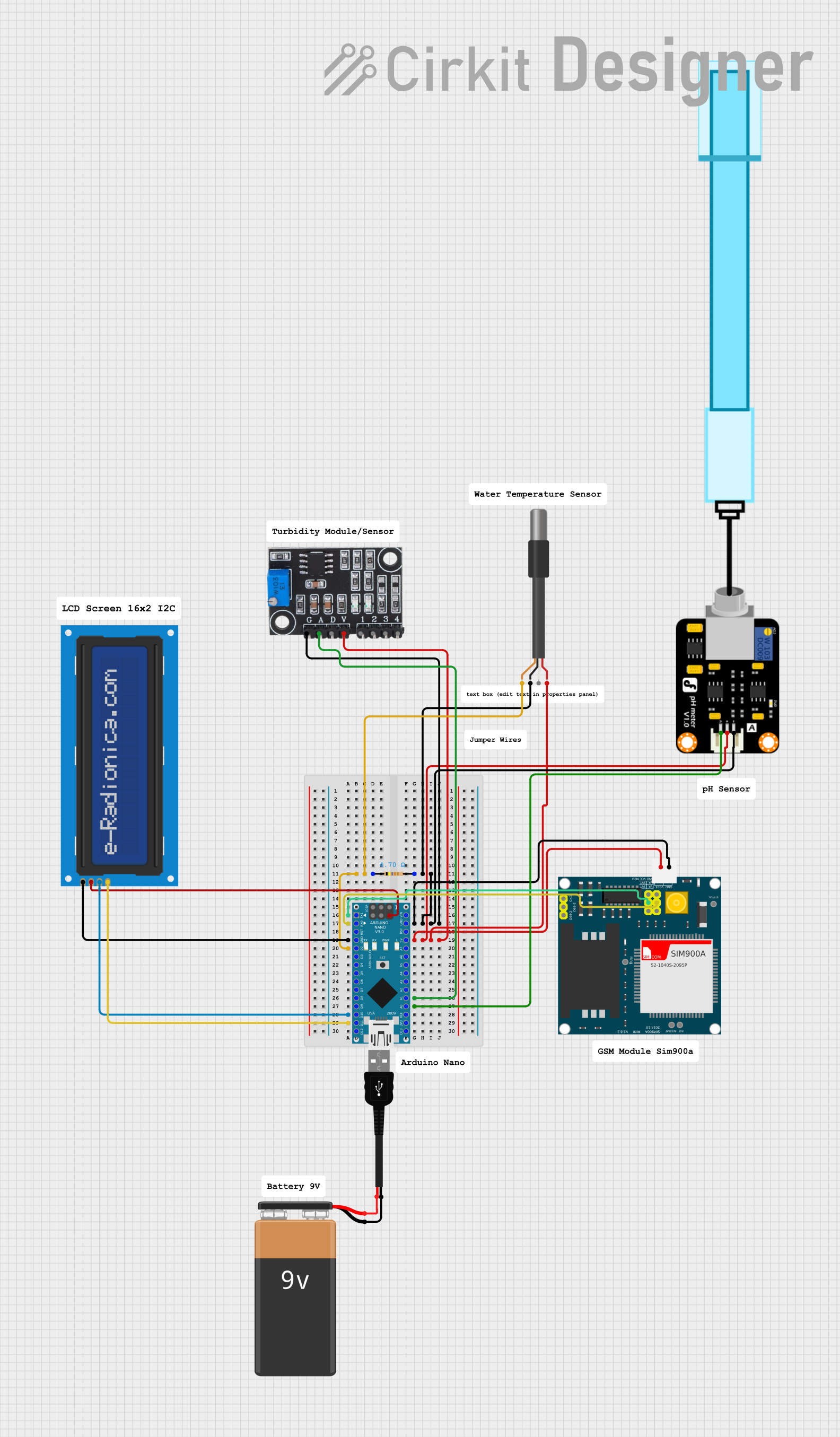
Explore Projects Built with Probe
Common Applications and Use Cases
- Measuring voltage levels in circuits
- Debugging and troubleshooting electronic devices
- Testing signal integrity in communication systems
- Oscilloscope and multimeter measurements
- Prototyping and circuit development
Technical Specifications
The following table outlines the key technical details of the probe manufactured by me, with part ID 00112:
| Parameter | Specification |
|---|---|
| Manufacturer | me |
| Part ID | 00112 |
| Maximum Voltage Rating | 600V DC |
| Maximum Current Rating | 10A |
| Impedance | 10MΩ |
| Bandwidth | 100 MHz |
| Connector Type | BNC (Bayonet Neill–Concelman) |
| Cable Length | 1.2 meters |
| Tip Type | Replaceable sharp metal tip |
| Compatibility | Oscilloscopes, multimeters, and other test equipment |
Pin Configuration and Descriptions
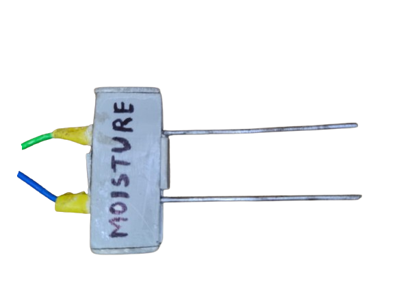
The probe does not have traditional pins but includes the following key components:
| Component | Description |
|---|---|
| Probe Tip | The sharp metal tip used to make contact with the test point in the circuit. |
| Ground Clip | A clip used to connect the probe to the circuit's ground for accurate readings. |
| BNC Connector | The connector used to attach the probe to test equipment like oscilloscopes. |
| Adjustment Trimmer | A small screw used to calibrate the probe for accurate signal measurements. |
Usage Instructions
How to Use the Probe in a Circuit
- Connect the Probe to the Test Equipment: Attach the BNC connector of the probe to the input port of your oscilloscope or multimeter.
- Attach the Ground Clip: Secure the ground clip to the circuit's ground point to ensure accurate and stable measurements.
- Position the Probe Tip: Place the probe tip on the test point in the circuit where you want to measure the signal.
- Adjust the Probe: If necessary, use the adjustment trimmer to calibrate the probe for optimal signal fidelity.
- Take Measurements: Observe the readings on your test equipment and analyze the signal.
Important Considerations and Best Practices
- Calibration: Always calibrate the probe before use to ensure accurate measurements, especially for high-frequency signals.
- Safety: Do not exceed the maximum voltage or current ratings of the probe to avoid damage or injury.
- Signal Integrity: Minimize noise by keeping the ground clip as short as possible and avoiding unnecessary loops in the cable.
- Maintenance: Regularly inspect the probe tip and ground clip for wear and replace them if necessary.
Example: Using the Probe with an Arduino UNO
To measure the voltage at a specific pin of an Arduino UNO, follow these steps:
- Connect the probe's BNC connector to an oscilloscope.
- Attach the ground clip to the Arduino's GND pin.
- Place the probe tip on the desired pin (e.g., pin 9).
- Use the following Arduino code to generate a PWM signal on pin 9 for testing:
// Arduino code to generate a PWM signal on pin 9
void setup() {
  pinMode(9, OUTPUT); // Set pin 9 as an output
}

void loop() {
  analogWrite(9, 128); // Generate a 50% duty cycle PWM signal
  delay(1000);         // Wait for 1 second
}
Troubleshooting and FAQs
Common Issues and Solutions
No Signal Detected
- Cause: The ground clip is not properly connected.
- Solution: Ensure the ground clip is securely attached to the circuit's ground.
Distorted Signal
- Cause: The probe is not calibrated.
- Solution: Use the adjustment trimmer to calibrate the probe.
Intermittent Readings
- Cause: Loose connections or damaged probe tip.
- Solution: Check all connections and replace the probe tip if necessary.
Excessive Noise in Measurements
- Cause: Long ground clip or cable loops.
- Solution: Shorten the ground clip and avoid unnecessary cable loops.
FAQs
Q: Can this probe be used with any oscilloscope?
A: Yes, as long as the oscilloscope has a compatible BNC input and the signal does not exceed the probe's voltage and bandwidth ratings.
Q: How often should I calibrate the probe?
A: It is recommended to calibrate the probe before each use, especially for high-frequency measurements.
Q: Can I replace the probe tip?
A: Yes, the probe tip is replaceable. Ensure you use a compatible replacement tip for optimal performance.
Q: Is this probe suitable for high-frequency signals?
A: Yes, the probe supports signals up to 100 MHz, making it suitable for most high-frequency applications.