How to Use Keypad: Examples, Pinouts, and Specs
Introduction
The HS-KEY4L keypad, manufactured by Chin, is an input device designed for user interaction in electronic systems. It consists of a matrix of keys or buttons that allow users to input data or commands. This component is widely used in applications requiring numeric or alphanumeric input, such as security systems, calculators, vending machines, and embedded systems.
Explore Projects Built with Keypad

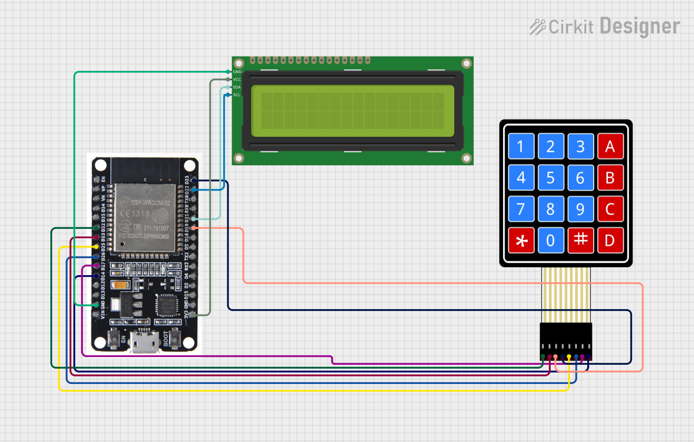
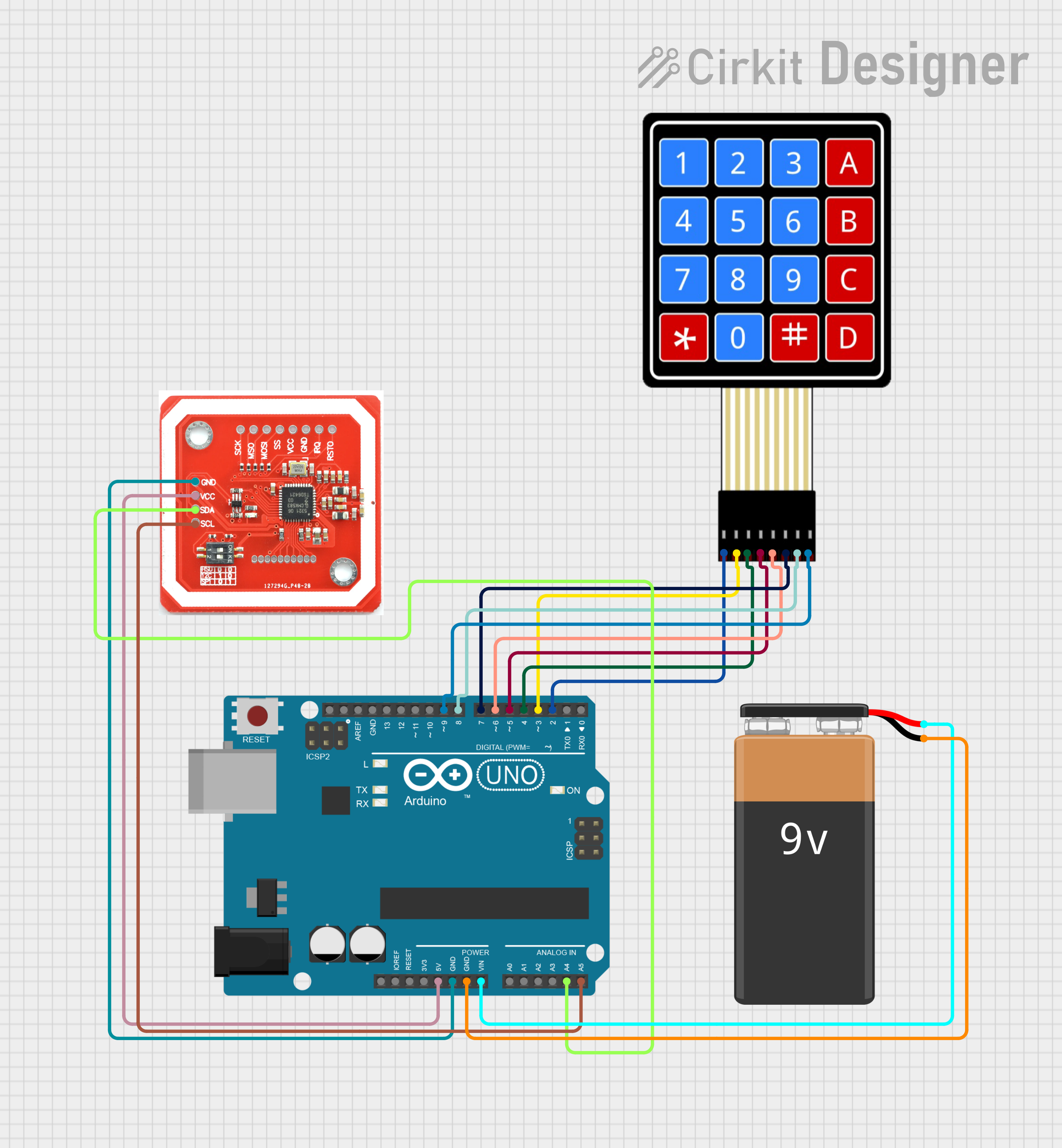

Explore Projects Built with Keypad
Common Applications
- Security systems (e.g., password entry for door locks)
- Home automation control panels
- Vending machines and kiosks
- Embedded systems requiring user input
- Calculator and handheld devices
Technical Specifications
The HS-KEY4L keypad is a 4x4 matrix keypad, meaning it has 4 rows and 4 columns, providing a total of 16 keys. Below are the key technical details:
Key Specifications
| Parameter | Value |
|---|---|
| Manufacturer | Chin |
| Part ID | HS-KEY4L |
| Keypad Layout | 4x4 Matrix |
| Number of Keys | 16 |
| Operating Voltage | 3.3V to 5V |
| Maximum Current | 20mA |
| Keypad Dimensions | 70mm x 70mm |
| Connector Type | 8-pin header |
| Operating Temperature | -20°C to 70°C |
Pin Configuration
The HS-KEY4L keypad has 8 pins, corresponding to the 4 rows and 4 columns of the matrix. The pinout is as follows:
| Pin Number | Description | Notes |
|---|---|---|
| 1 | Row 1 (R1) | Connect to microcontroller GPIO |
| 2 | Row 2 (R2) | Connect to microcontroller GPIO |
| 3 | Row 3 (R3) | Connect to microcontroller GPIO |
| 4 | Row 4 (R4) | Connect to microcontroller GPIO |
| 5 | Column 1 (C1) | Connect to microcontroller GPIO |
| 6 | Column 2 (C2) | Connect to microcontroller GPIO |
| 7 | Column 3 (C3) | Connect to microcontroller GPIO |
| 8 | Column 4 (C4) | Connect to microcontroller GPIO |
Usage Instructions
How to Use the Keypad in a Circuit
Wiring the Keypad:
- Connect the 8 pins of the keypad to the GPIO pins of a microcontroller (e.g., Arduino UNO).
- Use pull-up or pull-down resistors if necessary to stabilize the input signals.
Matrix Scanning:
- The keypad operates using a matrix scanning technique. The microcontroller sends signals to the column pins and reads the row pins to detect which key is pressed.
Power Supply:
- Ensure the keypad is powered within its operating voltage range (3.3V to 5V). Exceeding this range may damage the component.
Arduino UNO Example Code
Below is an example of how to interface the HS-KEY4L keypad with an Arduino UNO using the Keypad library:
#include <Keypad.h>

// Define the rows and columns of the keypad
const byte ROWS = 4; // Four rows
const byte COLS = 4; // Four columns

// Define the keymap for the keypad
char keys[ROWS][COLS] = {
  {'1', '2', '3', 'A'},
  {'4', '5', '6', 'B'},
  {'7', '8', '9', 'C'},
  {'*', '0', '#', 'D'}
};

// Define the row and column pins connected to the Arduino
byte rowPins[ROWS] = {9, 8, 7, 6};    // Connect to R1, R2, R3, R4
byte colPins[COLS] = {5, 4, 3, 2};    // Connect to C1, C2, C3, C4

// Create the Keypad object
Keypad keypad = Keypad(makeKeymap(keys), rowPins, colPins, ROWS, COLS);

void setup() {
  Serial.begin(9600); // Initialize serial communication
  Serial.println("Keypad Test Ready");
}

void loop() {
  char key = keypad.getKey(); // Check if a key is pressed

  if (key) { // If a key is pressed, print it to the Serial Monitor
    Serial.print("Key Pressed: ");
    Serial.println(key);
  }
}
Important Considerations
- Debouncing: Keypads may produce multiple signals for a single press due to mechanical bouncing. Use software debouncing or libraries like
Keypadto handle this. - Pull-up Resistors: If the microcontroller's GPIO pins do not have internal pull-ups, external resistors may be required.
- Keypad Mounting: Ensure the keypad is securely mounted to avoid accidental key presses.
Troubleshooting and FAQs
Common Issues and Solutions
No Key Press Detected:
- Cause: Incorrect wiring or loose connections.
- Solution: Double-check the wiring and ensure all connections are secure.
Multiple Keys Detected for a Single Press:
- Cause: Mechanical bouncing or incorrect matrix scanning.
- Solution: Implement software debouncing or use the
Keypadlibrary.
Keys Not Responding:
- Cause: Damaged keypad or incorrect pin mapping.
- Solution: Verify the pin mapping in the code and test the keypad with a multimeter.
Random Key Presses Detected:
- Cause: Electrical noise or floating pins.
- Solution: Use pull-up or pull-down resistors to stabilize the signals.
FAQs
Q1: Can the HS-KEY4L keypad be used with a 3.3V microcontroller?
A1: Yes, the keypad operates within a voltage range of 3.3V to 5V, making it compatible with 3.3V systems.
Q2: How do I clean the keypad if it gets dirty?
A2: Use a soft, damp cloth to clean the surface. Avoid using harsh chemicals that may damage the keys.
Q3: Can I use fewer than 16 keys?
A3: Yes, you can leave some rows or columns unconnected, but ensure the code is updated accordingly.
Q4: Is the keypad waterproof?
A4: No, the HS-KEY4L is not waterproof. Avoid exposing it to moisture or liquids.