How to Use Speed measuring sensor: Examples, Pinouts, and Specs
Introduction
A speed measuring sensor is a device designed to measure the speed of an object, typically using technologies such as radar, laser, or ultrasonic waves. These sensors are widely used in various industries and applications, including automotive systems, industrial automation, sports performance analysis, and traffic monitoring. They provide accurate and reliable speed measurements, making them essential for systems that require precise motion tracking or velocity data.
Common applications include:
- Vehicle speed detection in traffic enforcement systems.
- Conveyor belt speed monitoring in industrial automation.
- Sports equipment and athlete performance analysis.
- Robotics and drone navigation systems.
Explore Projects Built with Speed measuring sensor
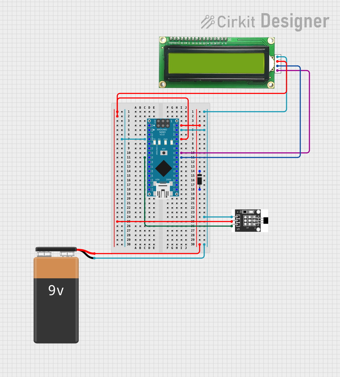
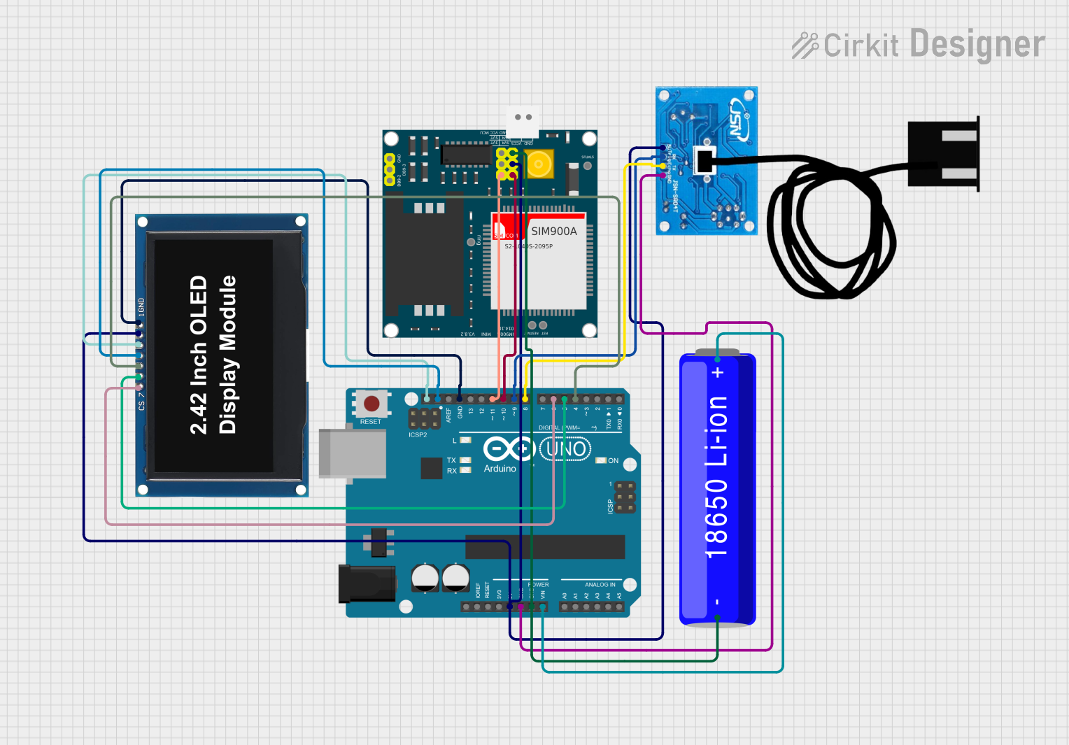
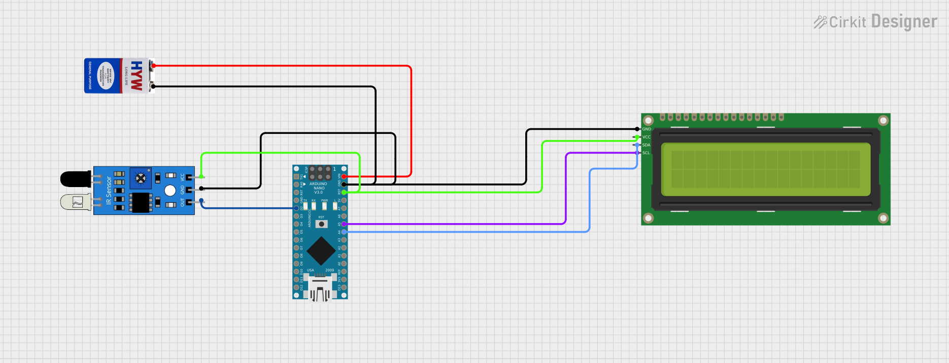

Explore Projects Built with Speed measuring sensor
Technical Specifications
Below are the general technical specifications for a typical speed measuring sensor. Note that specific models may vary slightly in their parameters.
| Parameter | Value |
|---|---|
| Operating Voltage | 3.3V to 5V |
| Operating Current | 10mA to 50mA |
| Measurement Range | 0.1 m/s to 300 m/s (depending on model) |
| Accuracy | ±0.1 m/s |
| Output Signal Type | Digital (PWM or frequency) or Analog |
| Operating Temperature | -20°C to 70°C |
| Communication Interface | GPIO, UART, or I2C (depending on model) |
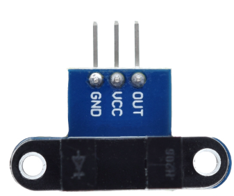
Pin Configuration
The pin configuration for a typical speed measuring sensor is as follows:
| Pin Name | Description |
|---|---|
| VCC | Power supply input (3.3V to 5V) |
| GND | Ground connection |
| OUT | Output signal (digital or analog, depending on model) |
| TRIG (optional) | Trigger input for initiating measurement (if applicable) |
Usage Instructions
How to Use the Speed Measuring Sensor in a Circuit
- Power the Sensor: Connect the VCC pin to a 3.3V or 5V power source and the GND pin to the ground of your circuit.
- Connect the Output: Attach the OUT pin to a microcontroller's GPIO pin or an analog input pin, depending on the sensor's output type.
- Trigger the Sensor (if applicable): If the sensor has a TRIG pin, send a HIGH signal to this pin to initiate a measurement.
- Read the Output: For digital sensors, measure the frequency or pulse width of the output signal to determine the speed. For analog sensors, read the voltage level corresponding to the speed.
Important Considerations and Best Practices
- Placement: Ensure the sensor is positioned correctly to face the moving object. Avoid obstructions that could interfere with the signal.
- Power Supply: Use a stable power source to avoid noise or inaccurate readings.
- Calibration: Some sensors may require calibration to ensure accurate measurements. Refer to the manufacturer's instructions for calibration procedures.
- Environmental Factors: Be mindful of environmental conditions such as temperature, humidity, and interference from other devices, which may affect performance.
Example: Using the Sensor with an Arduino UNO
Below is an example of how to use a speed measuring sensor with an Arduino UNO. This example assumes the sensor outputs a digital pulse signal proportional to the speed.
// Define the pin connected to the sensor's output
const int sensorPin = 2;

// Variables to store pulse duration and calculated speed
unsigned long pulseDuration;
float speed;

void setup() {
  pinMode(sensorPin, INPUT); // Set the sensor pin as input
  Serial.begin(9600);        // Initialize serial communication
}

void loop() {
  // Measure the duration of the HIGH pulse from the sensor
  pulseDuration = pulseIn(sensorPin, HIGH);

  // Calculate speed based on the pulse duration
  // (Assume a specific formula provided by the sensor's datasheet)
  speed = 1000.0 / pulseDuration; // Example formula (adjust as needed)

  // Print the speed to the Serial Monitor
  Serial.print("Speed: ");
  Serial.print(speed);
  Serial.println(" m/s");

  delay(500); // Wait for 500ms before the next reading
}
Note: Replace the formula in the code with the one provided in your sensor's datasheet for accurate speed calculations.
Troubleshooting and FAQs
Common Issues and Solutions
No Output Signal:
- Cause: Incorrect wiring or insufficient power supply.
- Solution: Double-check the connections and ensure the sensor is powered with the correct voltage.
Inaccurate Readings:
- Cause: Misalignment of the sensor or environmental interference.
- Solution: Reposition the sensor to face the moving object directly and eliminate sources of interference.
Intermittent Output:
- Cause: Unstable power supply or loose connections.
- Solution: Use a regulated power source and secure all connections.
Sensor Not Responding to Trigger:
- Cause: Incorrect trigger signal or damaged TRIG pin.
- Solution: Verify the trigger signal's voltage level and duration. Replace the sensor if the TRIG pin is damaged.
FAQs
Q: Can this sensor measure the speed of any object?
A: The sensor is designed to measure the speed of objects within its specified range and under suitable conditions. It may not work well with objects that are too small, too far, or moving erratically.
Q: How do I know if my sensor requires calibration?
A: Refer to the manufacturer's datasheet. Some sensors include a calibration procedure to ensure accurate readings.
Q: Can I use this sensor outdoors?
A: Many speed measuring sensors are designed for outdoor use, but ensure the sensor's operating temperature and environmental resistance match your requirements.
Q: What is the maximum distance the sensor can measure?
A: The maximum distance depends on the sensor model and technology (e.g., radar, laser, or ultrasonic). Check the datasheet for the specific range.
By following this documentation, you can effectively integrate and troubleshoot a speed measuring sensor in your projects.