How to Use VO617A: Examples, Pinouts, and Specs
Introduction
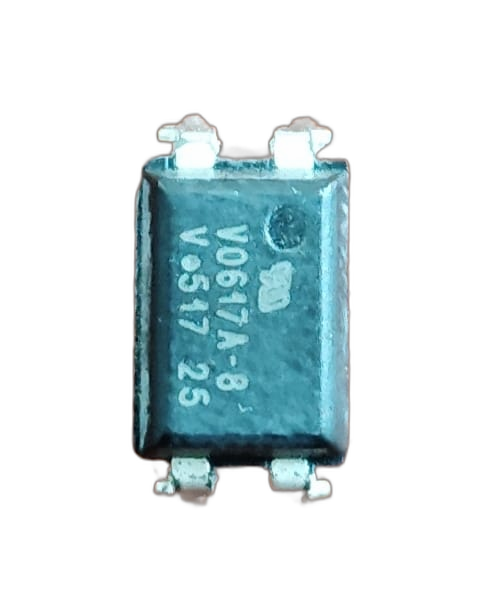
The VO617A, manufactured by Bholanath (Part ID: 235), is an optocoupler designed to provide electrical isolation between its input and output. It consists of an infrared light-emitting diode (LED) on the input side and a phototransistor on the output side. This configuration allows signals to be transmitted across the isolation barrier without any direct electrical connection, ensuring safety and noise immunity in sensitive circuits.
Explore Projects Built with VO617A
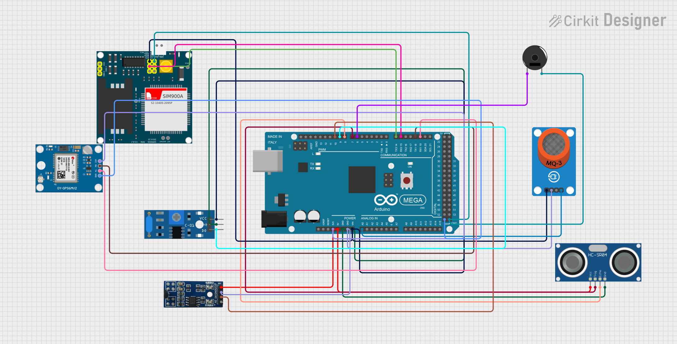
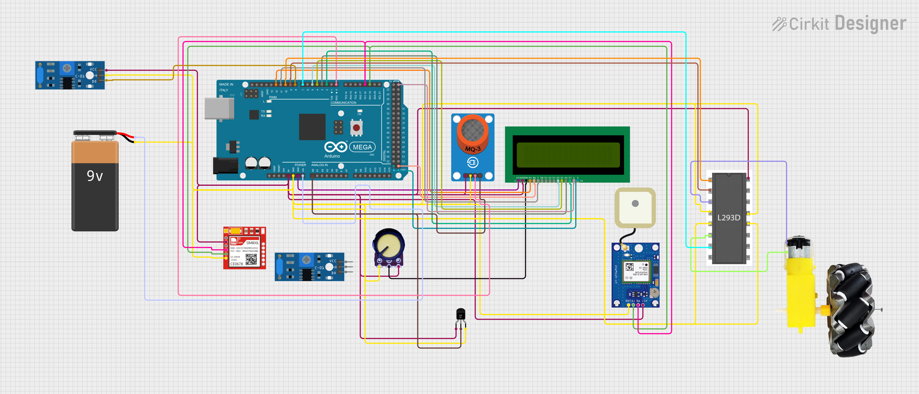
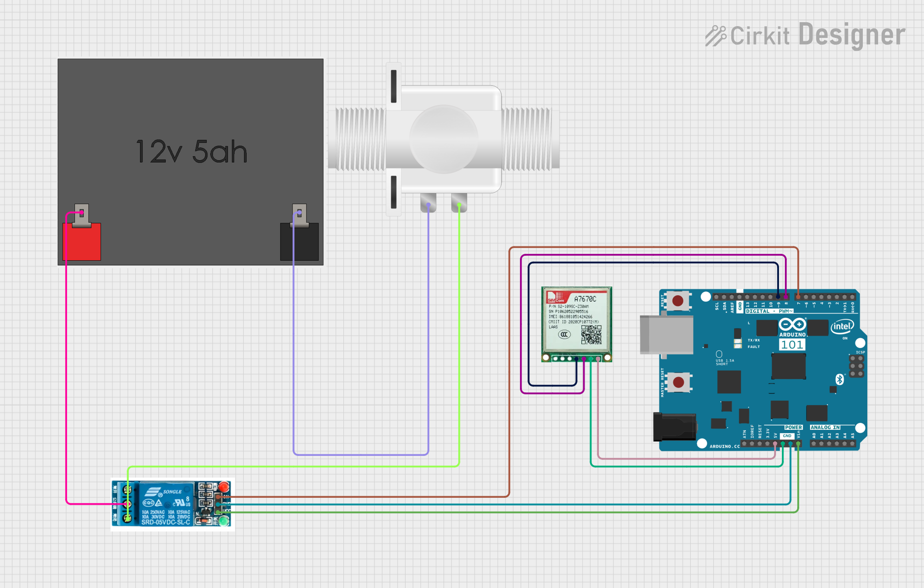
Explore Projects Built with VO617A
Common Applications and Use Cases
- Microcontroller Interfacing: Isolating microcontrollers from high-voltage circuits.
- Switching Power Supplies: Providing feedback across isolated sections.
- Industrial Automation: Protecting control systems from electrical noise.
- Signal Isolation: Preventing ground loops in communication systems.
- Motor Control: Isolating control signals from high-power motor drivers.
Technical Specifications
Key Technical Details
- Input LED Forward Voltage (VF): 1.2V (typical), 1.4V (maximum)
- Input LED Forward Current (IF): 10mA (typical), 50mA (maximum)
- Output Collector-Emitter Voltage (VCE): 70V (maximum)
- Output Collector Current (IC): 50mA (maximum)
- Current Transfer Ratio (CTR): 50% to 600% (depending on model and conditions)
- Isolation Voltage: 5000Vrms (minimum)
- Operating Temperature Range: -55°C to +110°C
Pin Configuration and Descriptions
The VO617A is typically available in a 4-pin DIP (Dual Inline Package). The pinout is as follows:
| Pin Number | Name | Description |
|---|---|---|
| 1 | Anode (A) | Positive terminal of the input LED. |
| 2 | Cathode (K) | Negative terminal of the input LED. |
| 3 | Emitter (E) | Emitter terminal of the phototransistor output. |
| 4 | Collector (C) | Collector terminal of the phototransistor output. |
Usage Instructions
How to Use the VO617A in a Circuit
Input Side (LED):
- Connect a current-limiting resistor in series with the LED (pins 1 and 2) to prevent excessive current. The resistor value can be calculated using Ohm's Law: [ R = \frac{V_{in} - V_F}{I_F} ] where (V_{in}) is the input voltage, (V_F) is the forward voltage of the LED, and (I_F) is the desired forward current.
Output Side (Phototransistor):
- Connect the phototransistor (pins 3 and 4) in the desired configuration:
- Common Emitter: Connect the emitter (pin 3) to ground and use the collector (pin 4) as the output.
- Common Collector: Connect the collector (pin 4) to the supply voltage through a pull-up resistor and use the emitter (pin 3) as the output.
- Connect the phototransistor (pins 3 and 4) in the desired configuration:
Power Supply:
- Ensure the input and output circuits are powered by separate, isolated power supplies to maintain electrical isolation.
Important Considerations and Best Practices
- Current Transfer Ratio (CTR): Select a VO617A variant with an appropriate CTR for your application. Higher CTR values are suitable for low-current input signals.
- Resistor Selection: Use precise resistor values to ensure the LED operates within its safe current range.
- Isolation Voltage: Do not exceed the specified isolation voltage to avoid breakdown of the optocoupler.
- Temperature Effects: Be aware that CTR and other parameters may vary with temperature. Design your circuit to accommodate these variations.
Example: Connecting VO617A to an Arduino UNO
The following example demonstrates how to use the VO617A to isolate a digital input signal for an Arduino UNO.
Circuit Diagram
- Input Side: Connect a 5V signal to the LED (pins 1 and 2) through a 330Ω resistor.
- Output Side: Connect the phototransistor (pins 3 and 4) in a common emitter configuration. Use a 10kΩ pull-up resistor on the collector (pin 4).
Arduino Code
// Define the input pin for the optocoupler output
const int optoInputPin = 2; // Digital pin 2 on Arduino

void setup() {
  pinMode(optoInputPin, INPUT); // Set the optocoupler output as input
  Serial.begin(9600);          // Initialize serial communication
}

void loop() {
  int signalState = digitalRead(optoInputPin); // Read the optocoupler output

  // Print the signal state to the Serial Monitor
  if (signalState == HIGH) {
    Serial.println("Signal HIGH: Input detected");
  } else {
    Serial.println("Signal LOW: No input detected");
  }

  delay(500); // Wait for 500ms before the next reading
}
Troubleshooting and FAQs
Common Issues and Solutions
LED Not Lighting Up:
- Cause: Insufficient input current or incorrect resistor value.
- Solution: Verify the resistor value and ensure the input voltage is sufficient to drive the LED.
No Output Signal:
- Cause: Incorrect wiring on the output side or insufficient pull-up resistor value.
- Solution: Check the output connections and use a pull-up resistor with an appropriate value (e.g., 10kΩ).
Signal Distortion or Noise:
- Cause: High-frequency noise or improper grounding.
- Solution: Use decoupling capacitors and ensure proper grounding in the circuit.
Exceeding Isolation Voltage:
- Cause: High voltage spikes or surges.
- Solution: Use transient voltage suppressors (TVS) or other protection devices to limit voltage spikes.
FAQs
Q: Can the VO617A be used for AC signal isolation?
A: Yes, but you will need to use a bridge rectifier or similar circuit to convert the AC signal to DC for the LED input.Q: What is the maximum switching speed of the VO617A?
A: The VO617A has a typical switching speed of 3µs to 5µs, making it suitable for low- to medium-speed applications.Q: Can I use the VO617A for analog signal transmission?
A: The VO617A is primarily designed for digital signals. Analog signal transmission may result in distortion due to the non-linear characteristics of the phototransistor.Q: How do I calculate the pull-up resistor value for the output?
A: The pull-up resistor value depends on the supply voltage and desired output current. A typical value is 10kΩ for 5V systems.