How to Use 4 channel relay module 5V JD-VCC: Examples, Pinouts, and Specs
Introduction
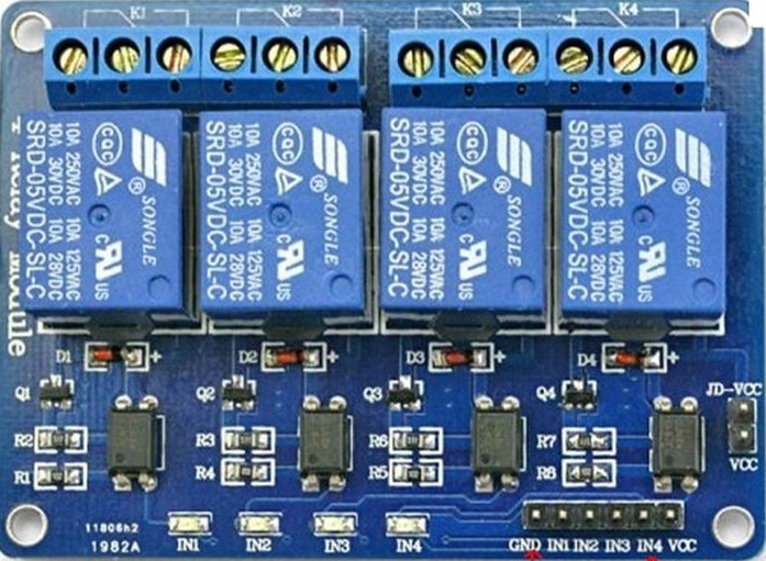
The 4 Channel Relay Module 5V JD-VCC is an electronic component designed to control up to four independent devices using low-power control signals. It operates on a 5V power supply and features an optocoupler-based isolation mechanism, ensuring safe and reliable operation in automation and control systems. The JD-VCC pin allows the relay power to be isolated from the control signal, reducing electrical noise and protecting sensitive microcontrollers.
Explore Projects Built with 4 channel relay module 5V JD-VCC


Explore Projects Built with 4 channel relay module 5V JD-VCC
Common Applications and Use Cases
- Home automation systems (e.g., controlling lights, fans, or appliances)
- Industrial automation and control
- Robotics and IoT projects
- Switching high-power devices (e.g., motors, pumps) with low-power microcontrollers
- Smart home projects integrated with Arduino, Raspberry Pi, or other microcontrollers
Technical Specifications
Key Technical Details
- Operating Voltage (Control Signal): 5V DC
- Relay Voltage (JD-VCC): 5V DC
- Trigger Current (per channel): 15-20mA
- Relay Type: SPDT (Single Pole Double Throw)
- Maximum Load (per channel):
- AC: 250V at 10A
- DC: 30V at 10A
- Optocoupler Isolation: Yes
- Number of Channels: 4
- Dimensions: Approximately 75mm x 55mm x 20mm
- Indicator LEDs: One per channel (lights up when the relay is active)
Pin Configuration and Descriptions
The module has two sets of pins: control pins and relay output terminals.
Control Pins
| Pin Name | Description |
|---|---|
| VCC | Connect to the 5V power supply of the microcontroller. |
| GND | Ground connection. |
| IN1 | Control signal for Relay 1 (active LOW). |
| IN2 | Control signal for Relay 2 (active LOW). |
| IN3 | Control signal for Relay 3 (active LOW). |
| IN4 | Control signal for Relay 4 (active LOW). |
| JD-VCC | Power supply for the relay coils (5V). |
| Jumper Cap | Used to connect VCC and JD-VCC for shared power. Remove for isolated operation. |
Relay Output Terminals
Each relay has three output terminals:
| Terminal | Description |
|---|---|
| NO (Normally Open) | Open circuit when the relay is inactive; closed when the relay is active. |
| COM (Common) | Common terminal for the relay. |
| NC (Normally Closed) | Closed circuit when the relay is inactive; open when the relay is active. |
Usage Instructions
How to Use the Component in a Circuit
Power the Module:
- Connect the VCC pin to a 5V power supply and GND to ground.
- For isolated operation, connect a separate 5V power supply to JD-VCC and remove the jumper cap.
Connect the Control Signals:
- Connect the IN1, IN2, IN3, and IN4 pins to the digital output pins of a microcontroller (e.g., Arduino).
- The relays are triggered by a LOW signal (0V).
Connect the Load:
- For each relay, connect the device you want to control to the NO, NC, and COM terminals as needed.
- Example: For a light bulb, connect one wire to COM and the other to NO.
Write the Control Code:
- Use the microcontroller to send LOW signals to the IN pins to activate the relays.
Important Considerations and Best Practices
- Isolation: For better safety and noise reduction, use a separate power supply for JD-VCC and remove the jumper cap.
- Inductive Loads: When switching inductive loads (e.g., motors), use a flyback diode across the load to prevent voltage spikes.
- Current Ratings: Ensure the connected load does not exceed the relay's maximum current and voltage ratings.
- Active LOW Trigger: Remember that the relays are activated by a LOW signal, not HIGH.
Example Code for Arduino UNO
// Example code to control a 4 Channel Relay Module with Arduino UNO
// This code toggles each relay ON and OFF with a 1-second delay.

#define RELAY1 2  // Connect IN1 to digital pin 2
#define RELAY2 3  // Connect IN2 to digital pin 3
#define RELAY3 4  // Connect IN3 to digital pin 4
#define RELAY4 5  // Connect IN4 to digital pin 5

void setup() {
  // Set relay pins as OUTPUT
  pinMode(RELAY1, OUTPUT);
  pinMode(RELAY2, OUTPUT);
  pinMode(RELAY3, OUTPUT);
  pinMode(RELAY4, OUTPUT);

  // Initialize all relays to OFF (HIGH state)
  digitalWrite(RELAY1, HIGH);
  digitalWrite(RELAY2, HIGH);
  digitalWrite(RELAY3, HIGH);
  digitalWrite(RELAY4, HIGH);
}

void loop() {
  // Turn each relay ON and OFF with a delay
  digitalWrite(RELAY1, LOW);  // Relay 1 ON
  delay(1000);                // Wait 1 second
  digitalWrite(RELAY1, HIGH); // Relay 1 OFF

  digitalWrite(RELAY2, LOW);  // Relay 2 ON
  delay(1000);                // Wait 1 second
  digitalWrite(RELAY2, HIGH); // Relay 2 OFF

  digitalWrite(RELAY3, LOW);  // Relay 3 ON
  delay(1000);                // Wait 1 second
  digitalWrite(RELAY3, HIGH); // Relay 3 OFF

  digitalWrite(RELAY4, LOW);  // Relay 4 ON
  delay(1000);                // Wait 1 second
  digitalWrite(RELAY4, HIGH); // Relay 4 OFF
}
Troubleshooting and FAQs
Common Issues and Solutions
Relays Not Activating:
- Cause: Insufficient power supply or incorrect wiring.
- Solution: Ensure the VCC and JD-VCC pins are connected to a stable 5V power source. Check the GND connection.
Microcontroller Resets When Relays Activate:
- Cause: Voltage spikes or insufficient power supply.
- Solution: Use a separate power supply for JD-VCC and remove the jumper cap. Add a capacitor across the power supply to stabilize it.
Relay LED Lights Up, but Load Does Not Switch:
- Cause: Incorrect wiring of the load to the relay terminals.
- Solution: Verify the connections to the NO, NC, and COM terminals.
Relays Stay ON or OFF Unexpectedly:
- Cause: Electrical noise or floating input pins.
- Solution: Use pull-up or pull-down resistors on the IN pins to stabilize the control signals.
FAQs
Can I use this module with a 3.3V microcontroller?
- Yes, but you may need a level shifter or transistor to ensure the control signals are compatible with the 5V relays.
What happens if I exceed the relay's current rating?
- Exceeding the current rating can damage the relay contacts and cause overheating. Always stay within the specified limits.
Can I control AC and DC loads simultaneously?
- Yes, as long as each load is connected to a separate relay and does not exceed the relay's ratings.
Is the module safe for high-voltage applications?
- The module is designed for high-voltage applications, but proper insulation and safety precautions must be followed.