
How to Use HMI DGUS: Examples, Pinouts, and Specs
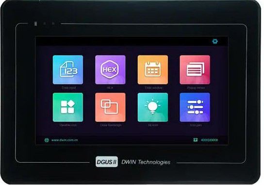
 Design with HMI DGUS in Cirkit Designer
Introduction
The HMI DGUS (Human-Machine Interface Digital Graphic User System) is a versatile user interface device designed to facilitate interaction between operators and machines or systems. It features a graphical display, often with touch screen capabilities, and supports customizable interfaces for a wide range of applications. The HMI DGUS is widely used in industrial automation, home automation, medical devices, and other systems requiring intuitive user interaction.
Explore Projects Built with HMI DGUS
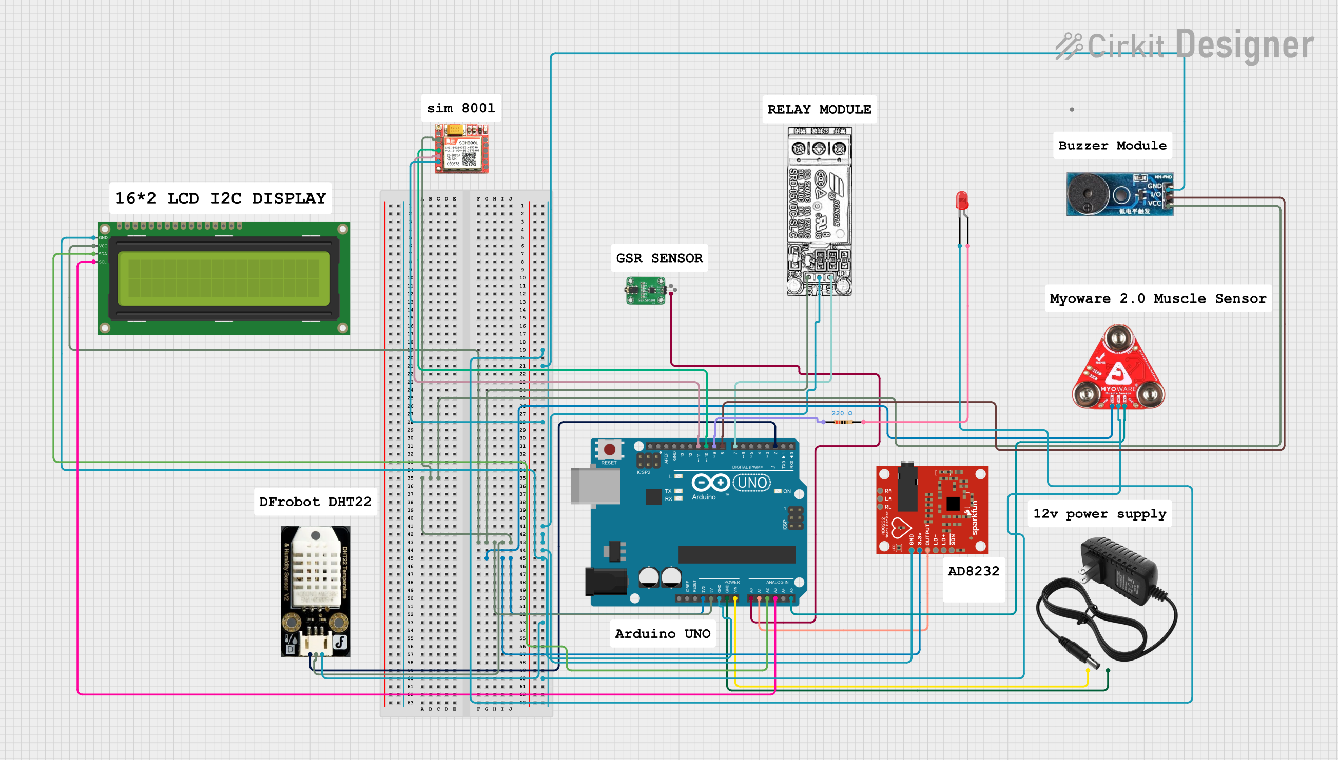 Open Project in Cirkit Designer
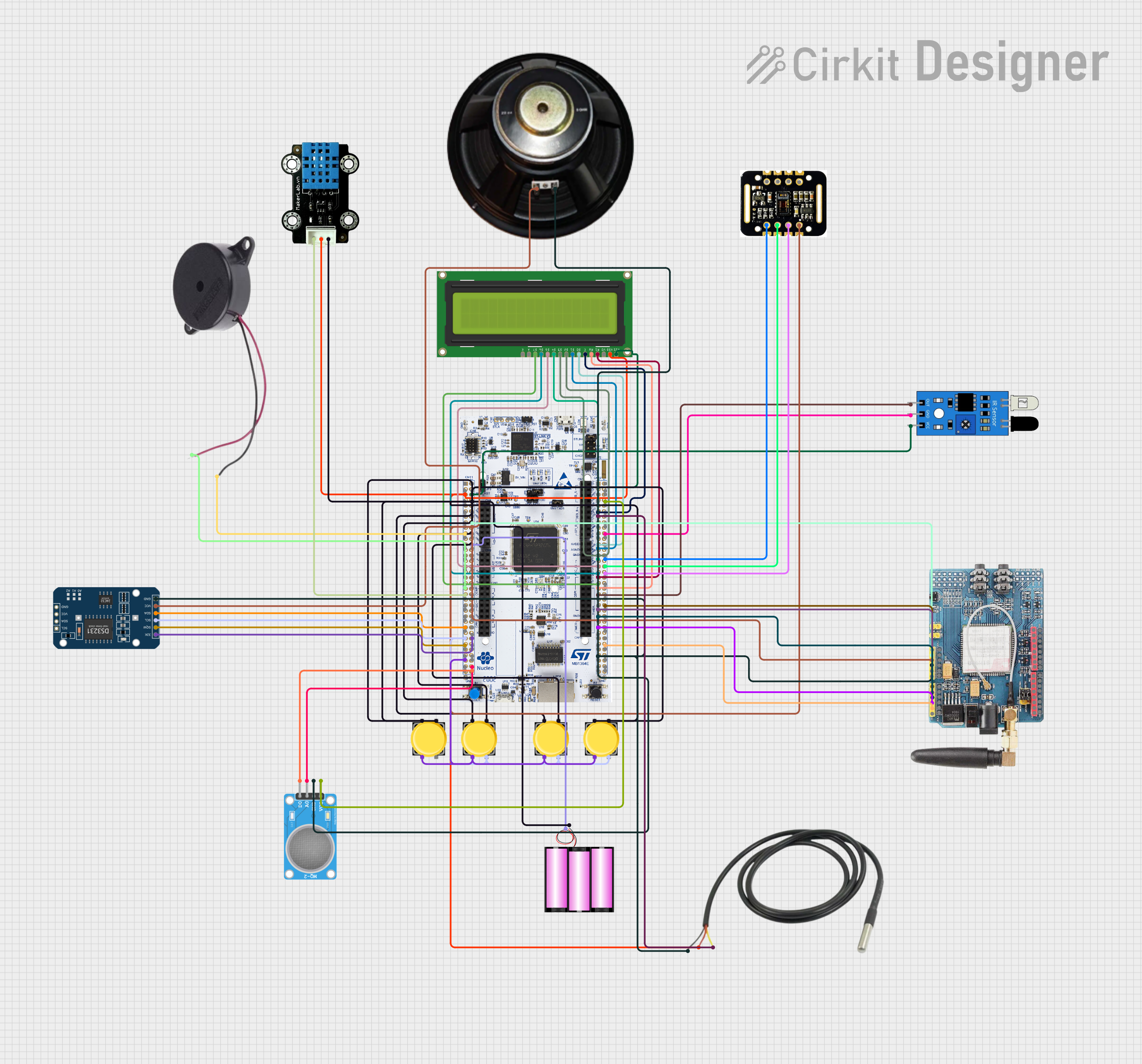 Open Project in Cirkit Designer
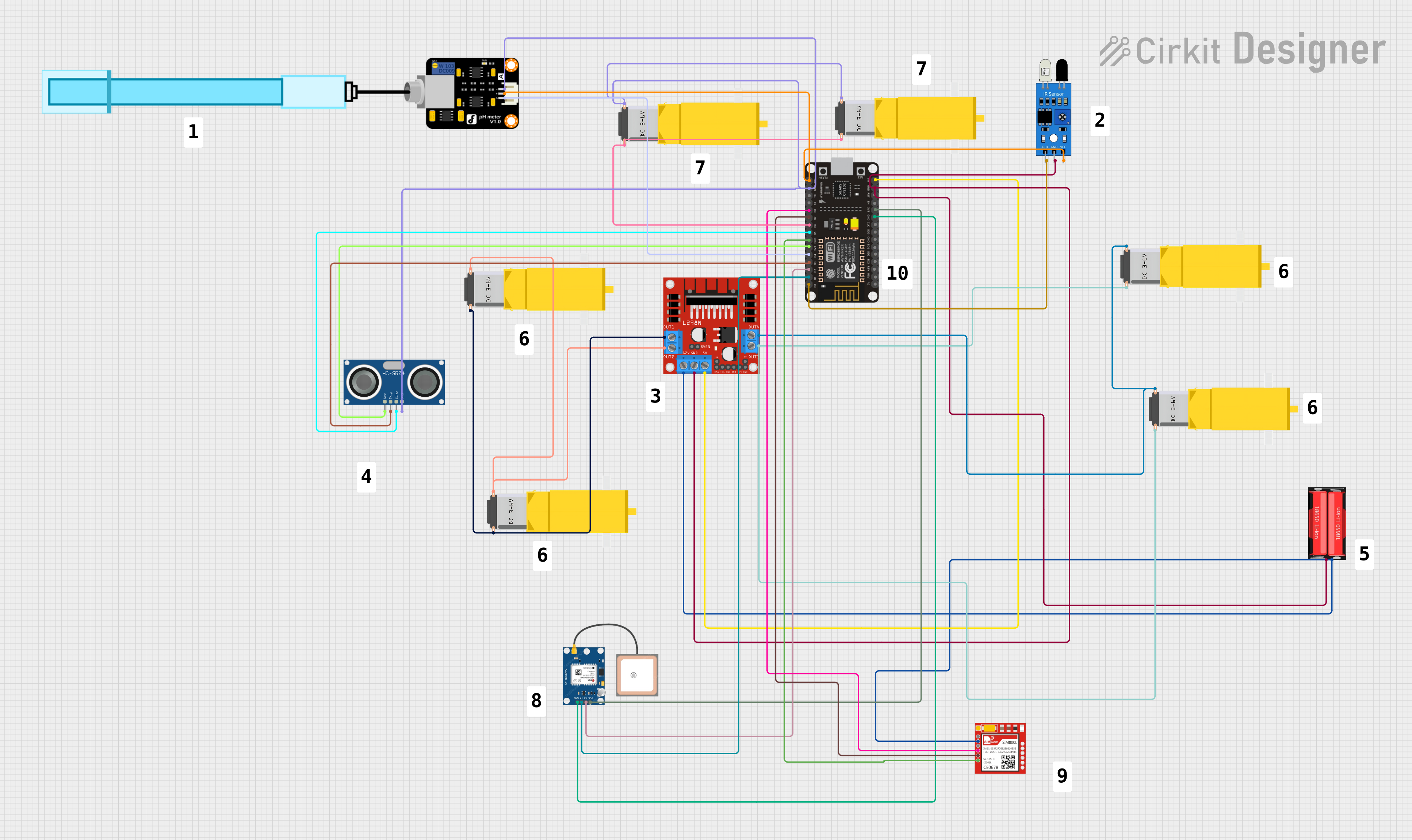 Open Project in Cirkit Designer
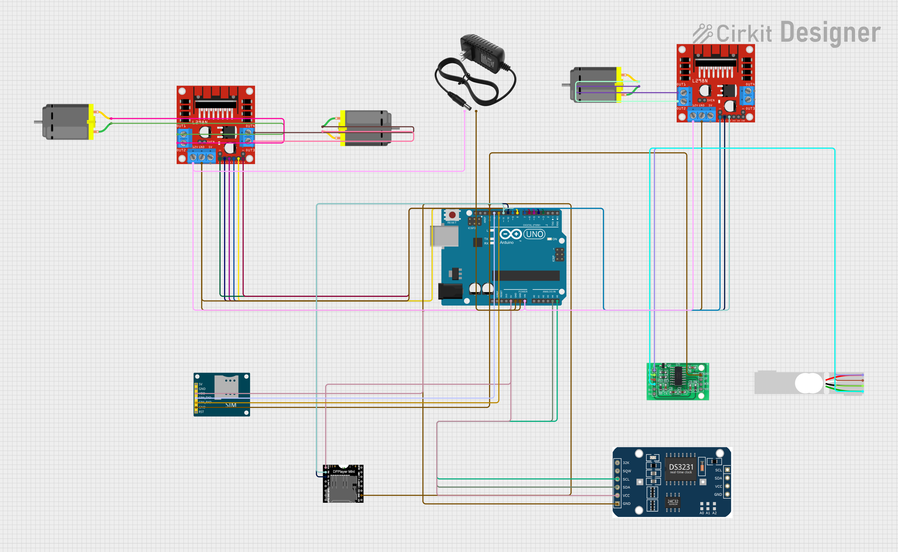 Open Project in Cirkit Designer
Explore Projects Built with HMI DGUS
Open Project in Cirkit DesignerOpen Project in Cirkit DesignerOpen Project in Cirkit DesignerOpen Project in Cirkit DesignerCommon Applications
- Industrial automation for controlling machinery and monitoring processes
- Home automation systems for managing smart devices
- Medical equipment interfaces for patient monitoring and diagnostics
- Automotive systems for dashboard displays
- Consumer electronics for user-friendly control panels
Technical Specifications
Key Technical Details
| Parameter | Specification |
|---|---|
| Manufacturer | HMI DGUS |
| Part ID | HMI DGUS |
| Display Type | TFT LCD with touch screen |
| Screen Sizes | 3.5", 4.3", 5", 7", 10.1", and larger |
| Resolution | Up to 1024x600 pixels (varies by model) |
| Input Voltage | 5V DC or 12V DC (model-dependent) |
| Communication Protocols | UART, RS232, RS485, CAN, Ethernet (varies by model) |
| Operating Temperature | -20°C to 70°C |
| Storage Temperature | -30°C to 80°C |
| Flash Memory | Up to 128MB (for storing GUI assets) |
| Touch Panel Type | Resistive or Capacitive (model-dependent) |
Pin Configuration and Descriptions
The pin configuration may vary depending on the specific model of the HMI DGUS. Below is a general example of the pinout for a typical HMI DGUS device:
| Pin Number | Pin Name | Description |
|---|---|---|
| 1 | VCC | Power supply input (5V or 12V DC) |
| 2 | GND | Ground connection |
| 3 | TXD | UART Transmit Data |
| 4 | RXD | UART Receive Data |
| 5 | RS485+ | RS485 Communication Positive Line |
| 6 | RS485- | RS485 Communication Negative Line |
| 7 | CAN_H | CAN Bus High Line (if supported) |
| 8 | CAN_L | CAN Bus Low Line (if supported) |
| 9 | RESET | Reset pin for restarting the device |
| 10 | GPIO | General Purpose Input/Output (varies by model) |
Usage Instructions
How to Use the HMI DGUS in a Circuit
- Power Supply: Connect the VCC and GND pins to a stable power source (5V or 12V DC, depending on the model).
- Communication: Use the appropriate communication protocol (e.g., UART, RS485, CAN) to interface the HMI DGUS with your microcontroller, PLC, or other hardware.
- GUI Design: Use the DGUS development software provided by the manufacturer to design and upload graphical user interfaces (GUIs) to the device.
- Wiring: Ensure proper wiring of communication lines (e.g., TXD, RXD for UART) and termination resistors for RS485 or CAN if required.
- Testing: Power on the device and test the communication and GUI functionality.
Important Considerations and Best Practices
- Voltage Compatibility: Verify the input voltage requirements for your specific HMI DGUS model to avoid damage.
- Communication Settings: Ensure that the baud rate, parity, and other communication parameters match between the HMI DGUS and the connected device.
- EMI Protection: Use shielded cables and proper grounding to minimize electromagnetic interference in industrial environments.
- Firmware Updates: Regularly check for firmware updates from the manufacturer to ensure optimal performance and compatibility.
- Touch Screen Calibration: If the touch screen is unresponsive or inaccurate, perform a calibration using the device's built-in tools.
Example: Connecting HMI DGUS to Arduino UNO
Below is an example of how to connect and program the HMI DGUS with an Arduino UNO using UART communication:
Wiring Diagram
| HMI DGUS Pin | Arduino UNO Pin |
|---|---|
| VCC | 5V |
| GND | GND |
| TXD | RX (Pin 0) |
| RXD | TX (Pin 1) |
Arduino Code
// Example code to send data to HMI DGUS via UART
// Ensure the baud rate matches the HMI DGUS settings

void setup() {
  Serial.begin(9600); // Initialize UART communication at 9600 baud
  delay(1000); // Wait for the HMI DGUS to initialize
}

void loop() {
  // Send a sample command to the HMI DGUS
  Serial.write(0x5A); // Start byte
  Serial.write(0xA5); // Command byte
  Serial.write(0x03); // Data length
  Serial.write(0x01); // Example data
  Serial.write(0x02); // Example data
  Serial.write(0x03); // Example data
  Serial.write(0x0F); // Checksum (example, calculate as needed)

  delay(1000); // Wait 1 second before sending the next command
}
Troubleshooting and FAQs
Common Issues and Solutions
HMI DGUS Not Powering On
- Cause: Incorrect power supply voltage or loose connections.
- Solution: Verify the input voltage and ensure secure connections to the VCC and GND pins.
No Communication Between HMI DGUS and Controller
- Cause: Mismatched baud rate or incorrect wiring.
- Solution: Check the communication settings and ensure proper wiring of TXD and RXD pins.
Touch Screen Not Responding
- Cause: Calibration issue or hardware fault.
- Solution: Perform a touch screen calibration or contact the manufacturer for support.
Display Freezes or Becomes Unresponsive
- Cause: Firmware bug or insufficient power supply.
- Solution: Update the firmware and ensure the power supply meets the device's requirements.
FAQs
Q: Can I use the HMI DGUS with a Raspberry Pi?
- A: Yes, the HMI DGUS can be connected to a Raspberry Pi using UART, RS485, or other supported communication protocols.
Q: How do I upload a GUI to the HMI DGUS?
- A: Use the DGUS development software provided by the manufacturer to design and upload GUI files via USB or SD card.
Q: What is the maximum cable length for RS485 communication?
- A: RS485 supports cable lengths up to 1200 meters, but this may vary depending on the baud rate and environmental factors.
Q: Can I use the HMI DGUS outdoors?
- A: Some models are designed for outdoor use, but ensure the device has the appropriate IP rating for your application.