How to Use IP2312: Examples, Pinouts, and Specs
Introduction
The IP2312 is a high-performance, low-power operational amplifier (op-amp) manufactured by Injoinic Technology. This versatile component is widely used in various signal processing and control systems due to its excellent performance characteristics. The IP2312 is designed to provide high gain, low offset voltage, and low power consumption, making it ideal for precision applications.
Explore Projects Built with IP2312


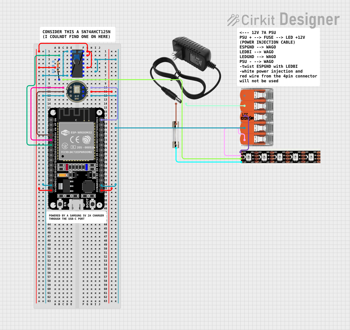

Explore Projects Built with IP2312
Common Applications and Use Cases
- Signal Amplification: Used to amplify weak signals in audio equipment, sensors, and instrumentation.
- Active Filters: Employed in designing low-pass, high-pass, band-pass, and band-stop filters.
- Voltage Followers: Used in buffer circuits to provide high input impedance and low output impedance.
- Comparators: Utilized in analog-to-digital conversion and other comparison-based applications.
- Oscillators: Implemented in waveform generation circuits.
Technical Specifications
Key Technical Details
| Parameter | Value |
|---|---|
| Supply Voltage | ±2V to ±18V |
| Input Offset Voltage | 1 mV (typical) |
| Input Bias Current | 20 nA (typical) |
| Gain Bandwidth | 1 MHz |
| Slew Rate | 0.5 V/µs |
| Output Current | ±20 mA |
| Power Consumption | 0.6 mW (typical) |
| Operating Temperature | -40°C to +85°C |
Pin Configuration and Descriptions
| Pin Number | Pin Name | Description |
|---|---|---|
| 1 | Offset N | Offset Null (Negative) |
| 2 | Inverting Input (−) | Inverting Input Terminal |
| 3 | Non-Inverting Input (+) | Non-Inverting Input Terminal |
| 4 | V- | Negative Power Supply |
| 5 | Offset P | Offset Null (Positive) |
| 6 | Output | Output Terminal |
| 7 | V+ | Positive Power Supply |
| 8 | NC | No Connection |
Usage Instructions
How to Use the Component in a Circuit
Power Supply: Connect the V+ pin to the positive supply voltage and the V- pin to the negative supply voltage. Ensure the supply voltage is within the specified range (±2V to ±18V).
Input Connections: Connect the signal to be amplified to the inverting (−) or non-inverting (+) input terminal, depending on the desired configuration (inverting or non-inverting amplifier).
Output Connection: Connect the output terminal to the load or the next stage of the circuit.
Offset Nulling: If precise offset voltage adjustment is required, connect a potentiometer between the Offset N and Offset P pins.
Important Considerations and Best Practices
- Decoupling Capacitors: Place decoupling capacitors (e.g., 0.1 µF) close to the power supply pins to filter out noise and ensure stable operation.
- Feedback Resistors: Use appropriate feedback resistors to set the desired gain in amplifier configurations.
- Thermal Management: Ensure adequate thermal management, especially in high-power applications, to prevent overheating.
- PCB Layout: Optimize PCB layout to minimize noise and interference, particularly in high-frequency applications.
Example Circuit with Arduino UNO
The following example demonstrates how to use the IP2312 as a voltage follower (buffer) with an Arduino UNO.
Circuit Diagram
Arduino UNO          IP2312
+5V --------------- V+
GND --------------- V-
A0 --------------- Non-Inverting Input (+)
Output ------------ A1
Arduino Code
// Arduino code to read an analog signal, buffer it using IP2312, and read the
// buffered signal

void setup() {
  Serial.begin(9600); // Initialize serial communication at 9600 baud rate
}

void loop() {
  int inputSignal = analogRead(A0); // Read the input signal from pin A0
  int bufferedSignal = analogRead(A1); // Read the buffered signal from pin A1

  // Print the input and buffered signals to the serial monitor
  Serial.print("Input Signal: ");
  Serial.print(inputSignal);
  Serial.print(" Buffered Signal: ");
  Serial.println(bufferedSignal);

  delay(1000); // Wait for 1 second before the next reading
}
Troubleshooting and FAQs
Common Issues Users Might Face
No Output Signal:
- Solution: Check the power supply connections and ensure the supply voltage is within the specified range. Verify that the input signal is correctly connected.
Output Signal Distortion:
- Solution: Ensure that the feedback network is correctly configured. Check for any noise or interference in the circuit and use decoupling capacitors if necessary.
High Offset Voltage:
- Solution: Use the offset nulling pins to adjust the offset voltage. Ensure that the potentiometer used for offset nulling is correctly connected.
Overheating:
- Solution: Ensure proper thermal management and avoid exceeding the maximum power dissipation. Use heat sinks if necessary.
FAQs
Q1: Can the IP2312 be used in single-supply applications?
- A1: Yes, the IP2312 can be used in single-supply applications by connecting the V- pin to ground and providing a positive supply voltage to the V+ pin.
Q2: What is the maximum output current of the IP2312?
- A2: The maximum output current of the IP2312 is ±20 mA.
Q3: How can I minimize noise in my circuit?
- A3: Use decoupling capacitors close to the power supply pins, optimize PCB layout, and use shielded cables for signal connections to minimize noise.
Q4: Can the IP2312 be used in high-frequency applications?
- A4: The IP2312 has a gain bandwidth of 1 MHz, making it suitable for low to moderate frequency applications. For high-frequency applications, consider using an op-amp with a higher gain bandwidth product.
This documentation provides a comprehensive overview of the IP2312 operational amplifier, including its technical specifications, usage instructions, and troubleshooting tips. Whether you are a beginner or an experienced user, this guide will help you effectively utilize the IP2312 in your electronic projects.