Cirkit Designer Logo
Cirkit Designer
Your all-in-one circuit design IDE
Home / 
Component Documentation

How to Use Wifi module ESP8266-01: Examples, Pinouts, and Specs

Image of Wifi module ESP8266-01
Cirkit Designer LogoDesign with Wifi module ESP8266-01 in Cirkit Designer

Introduction

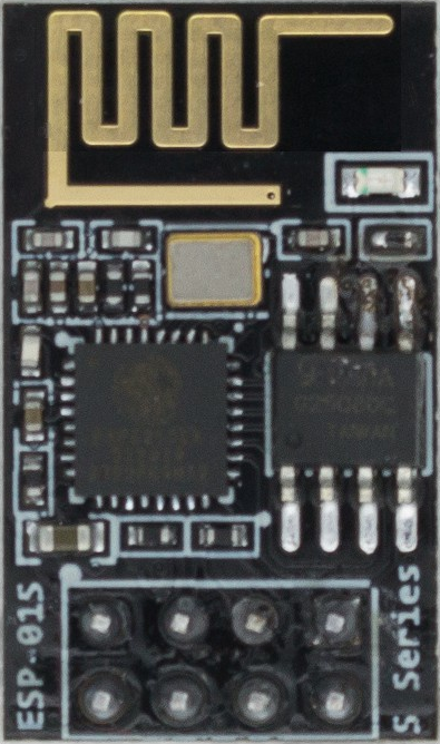
The ESP8266-01 is a highly integrated Wi-Fi module that offers a complete and self-contained networking solution, allowing it to either host an application or offload all Wi-Fi networking functions from another application processor. Manufactured by AZDelivery, the ESP8266-01 is based on the ESP8266 chip and is widely used in Internet of Things (IoT) applications due to its compact size, low cost, and robust feature set.

Explore Projects Built with Wifi module ESP8266-01

Use Cirkit Designer to design, explore, and prototype these projects online. Some projects support real-time simulation. Click "Open Project" to start designing instantly!
ESP8266 WiFi Module Serial Interface with Pushbutton Control
Image of esp01 progrmmer: A project utilizing Wifi module ESP8266-01 in a practical application
This circuit features an ESP8266 ESP-01 WiFi module interfaced with an Adafruit FTDI Friend for serial communication. The ESP8266's TXD and RXD pins are connected to the FTDI's RX and TX pins respectively, allowing for data exchange between the microcontroller and a computer. Additionally, a pushbutton is connected to the ESP8266's reset pin, enabling manual resets of the module.
Cirkit Designer LogoOpen Project in Cirkit Designer
Arduino UNO and ESP8266 WiFi Module Interaction System
Image of Copy of ESP-01 Arduino: A project utilizing Wifi module ESP8266-01 in a practical application
This circuit includes multiple Arduino UNO boards each interfaced with an ESP8266 ESP-01 WiFi module for potential wireless communication capabilities. The ESP8266 modules are powered and enabled for operation with necessary pull-up resistors and pushbuttons for user interaction, but the specific functionality is yet to be defined as the microcontroller code is currently empty.
Cirkit Designer LogoOpen Project in Cirkit Designer
ESP8266 NodeMCU with LoRa and RS-485 Communication and Ethernet Connectivity
Image of Wiring Diagram LoRa: A project utilizing Wifi module ESP8266-01 in a practical application
This circuit serves as a multi-protocol communication hub featuring two ESP8266 NodeMCUs for processing, each connected to a LoRa Ra-02 SX1278 for long-range wireless communication. One NodeMCU is also connected to an RS-485 module for serial communication and a W5500 Ethernet module for network connectivity, with MB102 modules supplying power.
Cirkit Designer LogoOpen Project in Cirkit Designer
ESP8266 and LoRa SX1278 Based Wireless Communication Module
Image of Receiver: A project utilizing Wifi module ESP8266-01 in a practical application
This circuit integrates a LoRa Ra-02 SX1278 module with an ESP8266 NodeMCU to enable long-range wireless communication. The ESP8266 NodeMCU handles the control and data processing, while the LoRa module provides the capability to transmit and receive data over long distances using LoRa technology.
Cirkit Designer LogoOpen Project in Cirkit Designer

Explore Projects Built with Wifi module ESP8266-01

Use Cirkit Designer to design, explore, and prototype these projects online. Some projects support real-time simulation. Click "Open Project" to start designing instantly!
Image of esp01 progrmmer: A project utilizing Wifi module ESP8266-01 in a practical application
ESP8266 WiFi Module Serial Interface with Pushbutton Control
This circuit features an ESP8266 ESP-01 WiFi module interfaced with an Adafruit FTDI Friend for serial communication. The ESP8266's TXD and RXD pins are connected to the FTDI's RX and TX pins respectively, allowing for data exchange between the microcontroller and a computer. Additionally, a pushbutton is connected to the ESP8266's reset pin, enabling manual resets of the module.
Cirkit Designer LogoOpen Project in Cirkit Designer
Image of Copy of ESP-01 Arduino: A project utilizing Wifi module ESP8266-01 in a practical application
Arduino UNO and ESP8266 WiFi Module Interaction System
This circuit includes multiple Arduino UNO boards each interfaced with an ESP8266 ESP-01 WiFi module for potential wireless communication capabilities. The ESP8266 modules are powered and enabled for operation with necessary pull-up resistors and pushbuttons for user interaction, but the specific functionality is yet to be defined as the microcontroller code is currently empty.
Cirkit Designer LogoOpen Project in Cirkit Designer
Image of Wiring Diagram LoRa: A project utilizing Wifi module ESP8266-01 in a practical application
ESP8266 NodeMCU with LoRa and RS-485 Communication and Ethernet Connectivity
This circuit serves as a multi-protocol communication hub featuring two ESP8266 NodeMCUs for processing, each connected to a LoRa Ra-02 SX1278 for long-range wireless communication. One NodeMCU is also connected to an RS-485 module for serial communication and a W5500 Ethernet module for network connectivity, with MB102 modules supplying power.
Cirkit Designer LogoOpen Project in Cirkit Designer
Image of Receiver: A project utilizing Wifi module ESP8266-01 in a practical application
ESP8266 and LoRa SX1278 Based Wireless Communication Module
This circuit integrates a LoRa Ra-02 SX1278 module with an ESP8266 NodeMCU to enable long-range wireless communication. The ESP8266 NodeMCU handles the control and data processing, while the LoRa module provides the capability to transmit and receive data over long distances using LoRa technology.
Cirkit Designer LogoOpen Project in Cirkit Designer

Common Applications and Use Cases

  • Smart home devices
  • Wi-Fi enabled sensors
  • Wireless data logging
  • Remote control systems
  • IoT prototypes and projects

Technical Specifications

Key Technical Details

  • Operating Voltage: 3.0V to 3.6V
  • Recommended Operating Voltage: 3.3V
  • Operating Current: Average ~80mA
  • Wireless Standard: 802.11 b/g/n
  • Frequency Range: 2.4 GHz - 2.5 GHz (2400M - 2483.5M)
  • Serial/UART baud rate: 115200 bps (default, can be changed)
  • Flash Memory: 1MB

Pin Configuration and Descriptions

Pin Number Name Description
1 GND Ground
2 GPIO2 General Purpose Input/Output 2
3 GPIO0 General Purpose Input/Output 0
4 RX UART Receive Pin
5 TX UART Transmit Pin
6 CH_PD Chip Power-down Pin. Active high.
7 RST Reset Pin. Active low.
8 VCC Power Supply (3.3V)

Usage Instructions

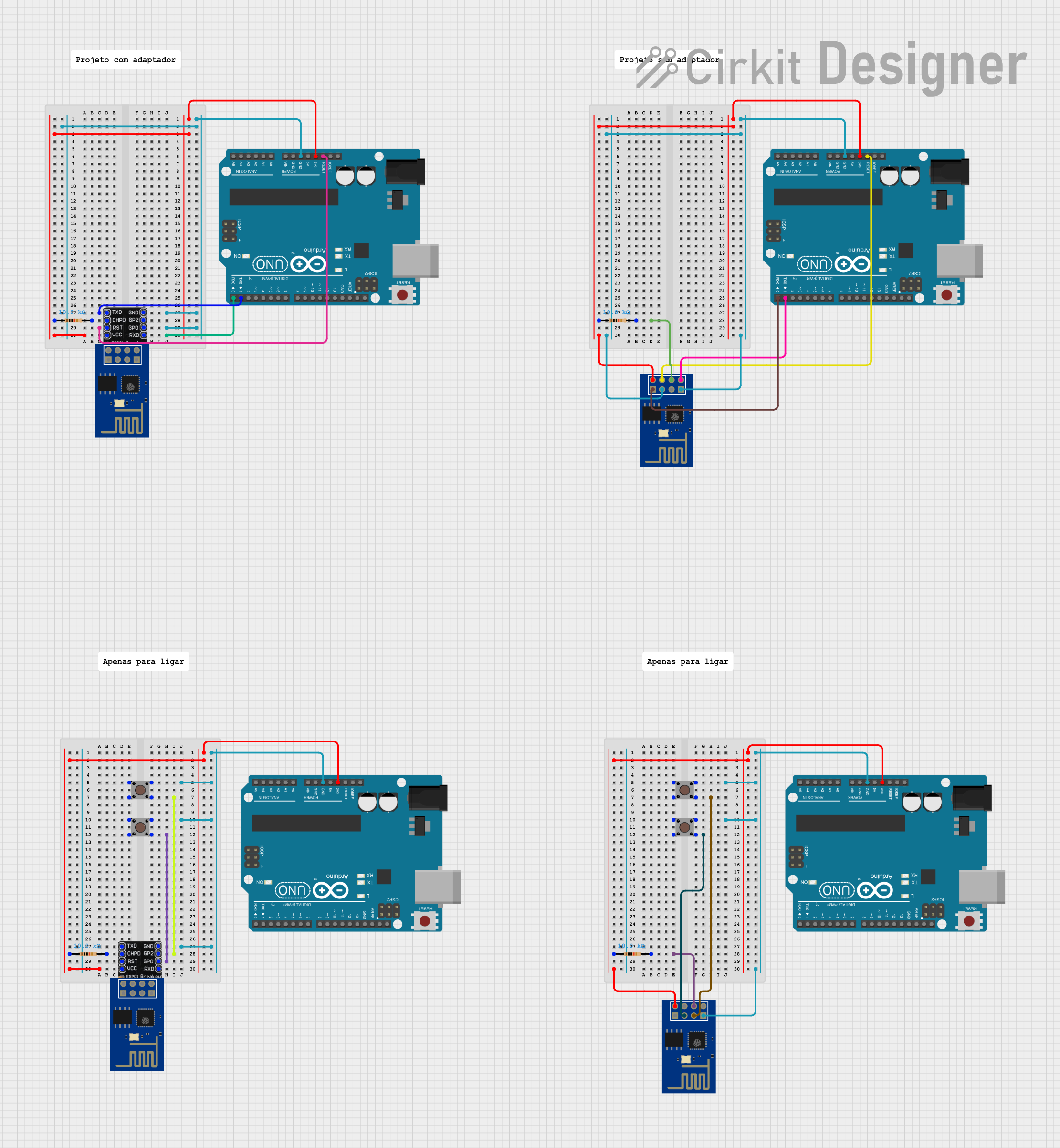
How to Use the Component in a Circuit

  1. Connect VCC to a stable 3.3V power supply.
  2. Connect GND to the ground of the power supply.
  3. Connect CH_PD to VCC to enable the chip.
  4. Connect RST to VCC through a pull-up resistor to prevent unwanted resets.
  5. Connect TX and RX to a serial converter or microcontroller UART pins for communication.
  6. GPIO0 and GPIO2 can be used for custom functions and must be pulled high for normal operation.

Important Considerations and Best Practices

  • Ensure that the power supply can deliver sufficient current for the module's operation.
  • Use a 3.3V logic level for UART communication to avoid damaging the module.
  • Avoid powering the module directly from a 5V source without a voltage regulator.
  • For stable operation, it is recommended to use an external antenna if the signal strength is weak.
  • When programming the module, GPIO0 must be grounded to enable the flash mode.

Troubleshooting and FAQs

Common Issues Users Might Face

  • Module does not power on: Check the power supply and connections to VCC and GND.
  • Cannot connect to Wi-Fi: Ensure the antenna is properly connected and the Wi-Fi credentials are correct.
  • Serial communication not working: Verify the baud rate and that TX/RX are not swapped.

Solutions and Tips for Troubleshooting

  • If the module is unresponsive, try a hard reset by pulling RST to GND momentarily.
  • For power issues, ensure that the power supply can deliver at least 250mA to the module.
  • Use external level shifters if interfacing with 5V logic microcontrollers.

FAQs

  • Q: Can the ESP8266-01 be used with Arduino? A: Yes, it can be interfaced with an Arduino using serial communication (UART).

  • Q: How do I program the ESP8266-01? A: The module can be programmed using the Arduino IDE or other development platforms that support the ESP8266.

  • Q: What is the default firmware on the ESP8266-01? A: The module typically comes with AT firmware for basic Wi-Fi and networking commands.

Example Code for Arduino UNO

#include <SoftwareSerial.h>

// RX, TX pins for connecting to ESP8266-01
const int RX_PIN = 2;
const int TX_PIN = 3;

// Set up a software serial port
SoftwareSerial esp8266(RX_PIN, TX_PIN);

void setup() {
  // Start the software serial communication
  esp8266.begin(115200);
  Serial.begin(115200);
  
  // Send AT command to check if the module is responding
  esp8266.println("AT");
}

void loop() {
  // Check if the module has responded with "OK"
  if (esp8266.available()) {
    String response = esp8266.readString();
    Serial.println(response);
  }
  
  // Check if there is any data from the Serial Monitor
  if (Serial.available()) {
    String command = Serial.readString();
    esp8266.println(command);
  }
}

Note: This example assumes that the ESP8266-01 is already configured to the correct baud rate and is in a state to accept AT commands. If you are using a different baud rate or need to change settings, adjust the esp8266.begin(115200); line accordingly.