Cirkit Designer
Your all-in-one circuit design IDE
Home /
Component Documentation
How to Use OPENMV4-CAM-H7: Examples, Pinouts, and Specs
Introduction
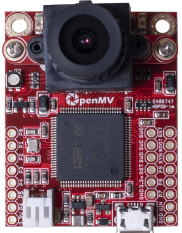
The OPENMV4-CAM-H7 is a compact, low-power microcontroller board with an integrated camera module, designed by Seeed Studio for machine vision applications. It features an ARM Cortex-M7 processor, capable of running complex algorithms for image processing, object detection, and more. This versatile component is ideal for projects involving computer vision, robotics, and automation.
Explore Projects Built with OPENMV4-CAM-H7
ESP32-CAM Controlled Servo Array with IR Sensing and OLED Feedback
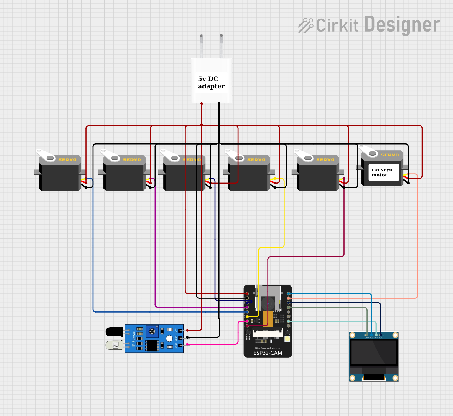
This circuit features an ESP32-CAM microcontroller connected to multiple servo motors and an IR sensor, with a 0.96" OLED display for output. The servos are controlled by the ESP32-CAM via individual IO pins, allowing for independent movement, while the IR sensor's output is also connected to the microcontroller for input sensing. The entire circuit is powered by a 5V adapter, with common ground and power lines for all components.
Arduino UNO-Based Object Detection System with OLED Display and OV7670 Camera Module
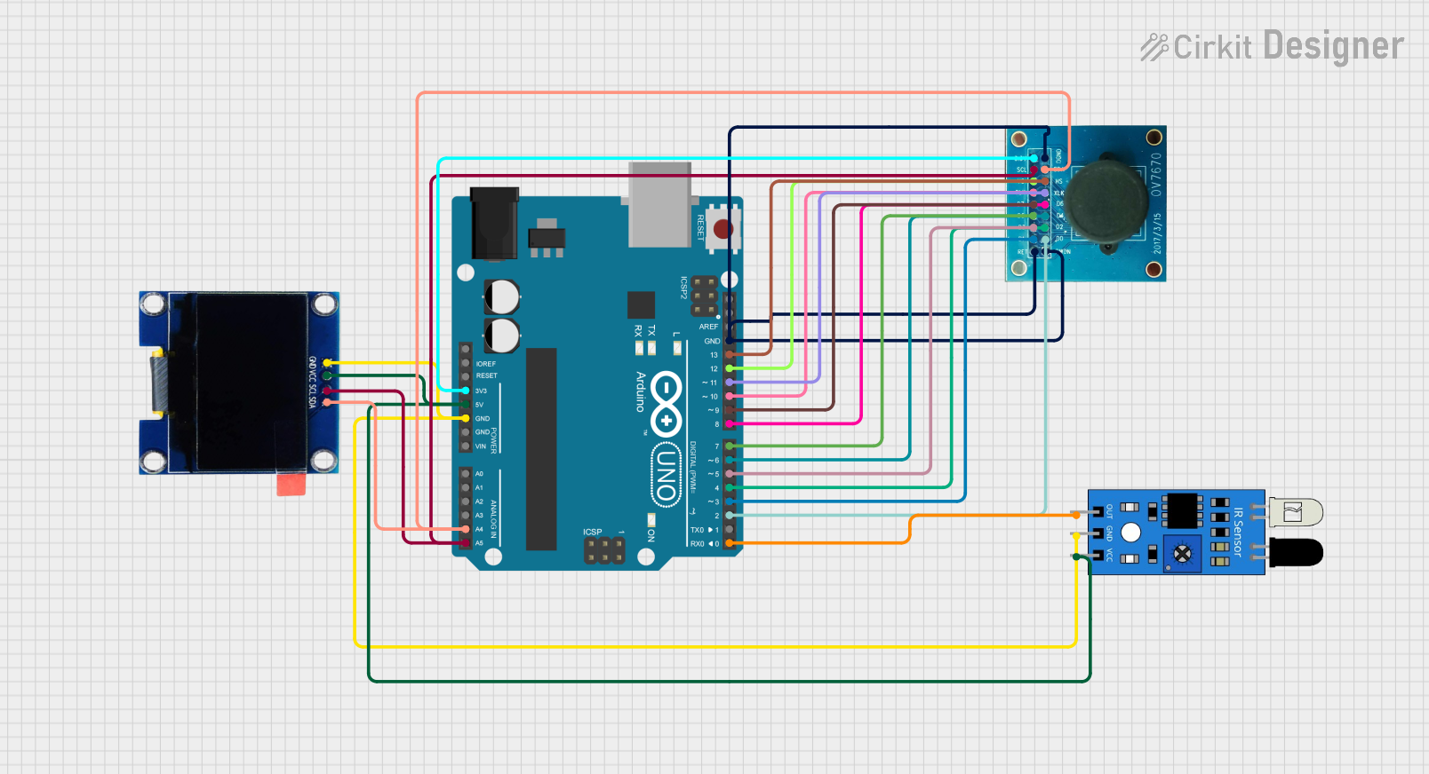
This circuit features an Arduino UNO microcontroller interfaced with an OLED display, an OV7670 camera module, and an IR sensor. The Arduino manages image capture from the OV7670 when the IR sensor detects an object, and then displays the image on the OLED screen. The Arduino's digital and analog pins are used to control the camera and communicate with the OLED via I2C, while the IR sensor output is connected to one of the Arduino's digital pins.
Arduino UNO-Based Smart Surveillance System with ArduCam Mega, OV7670, and Wi-Fi Connectivity
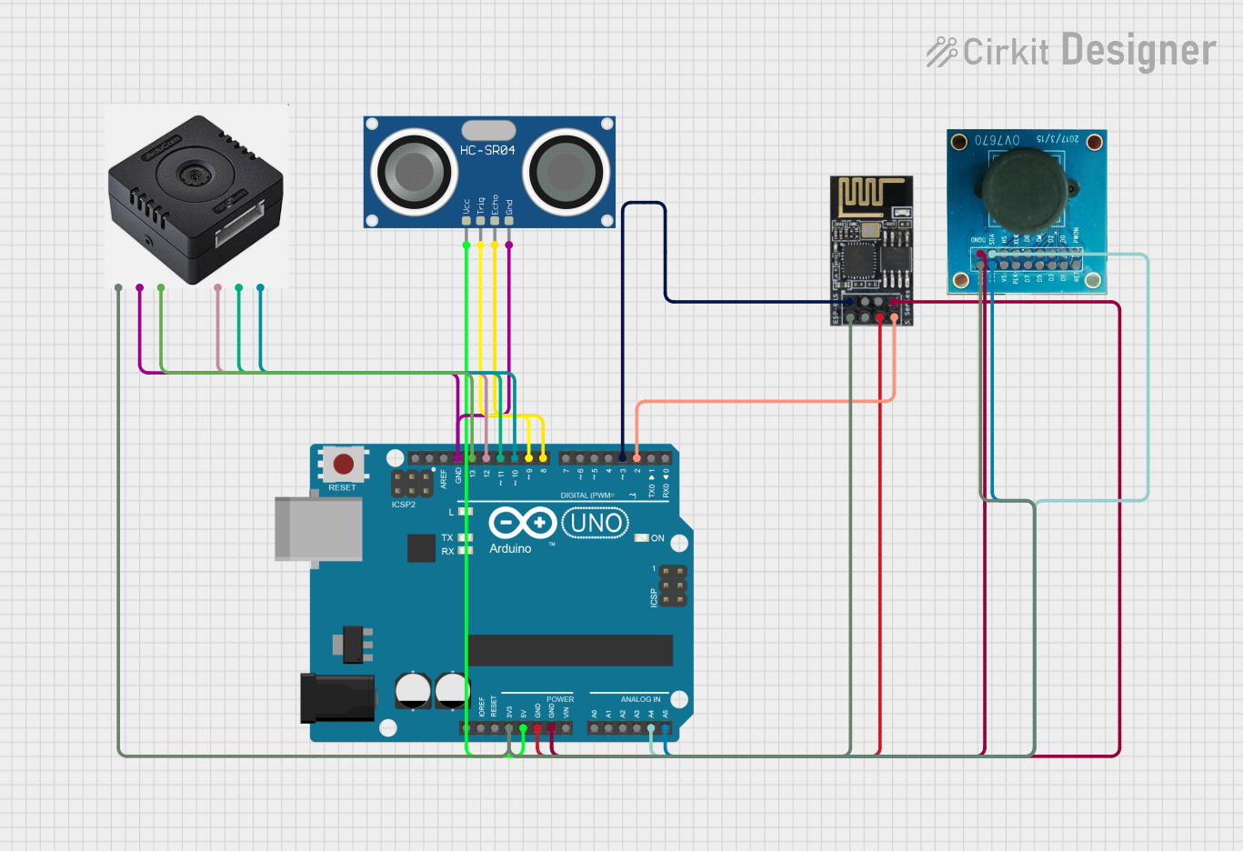
This circuit integrates an Arduino UNO with an ArduCam Mega, an OV7670 camera, an HC-SR04 ultrasonic sensor, and a WiFi module ESP8266-01. The system captures images and distance measurements, processes the data, and transmits it over WiFi to a connected device.
Arduino UNO Based IR Object Detection with OV7670 Camera Interface
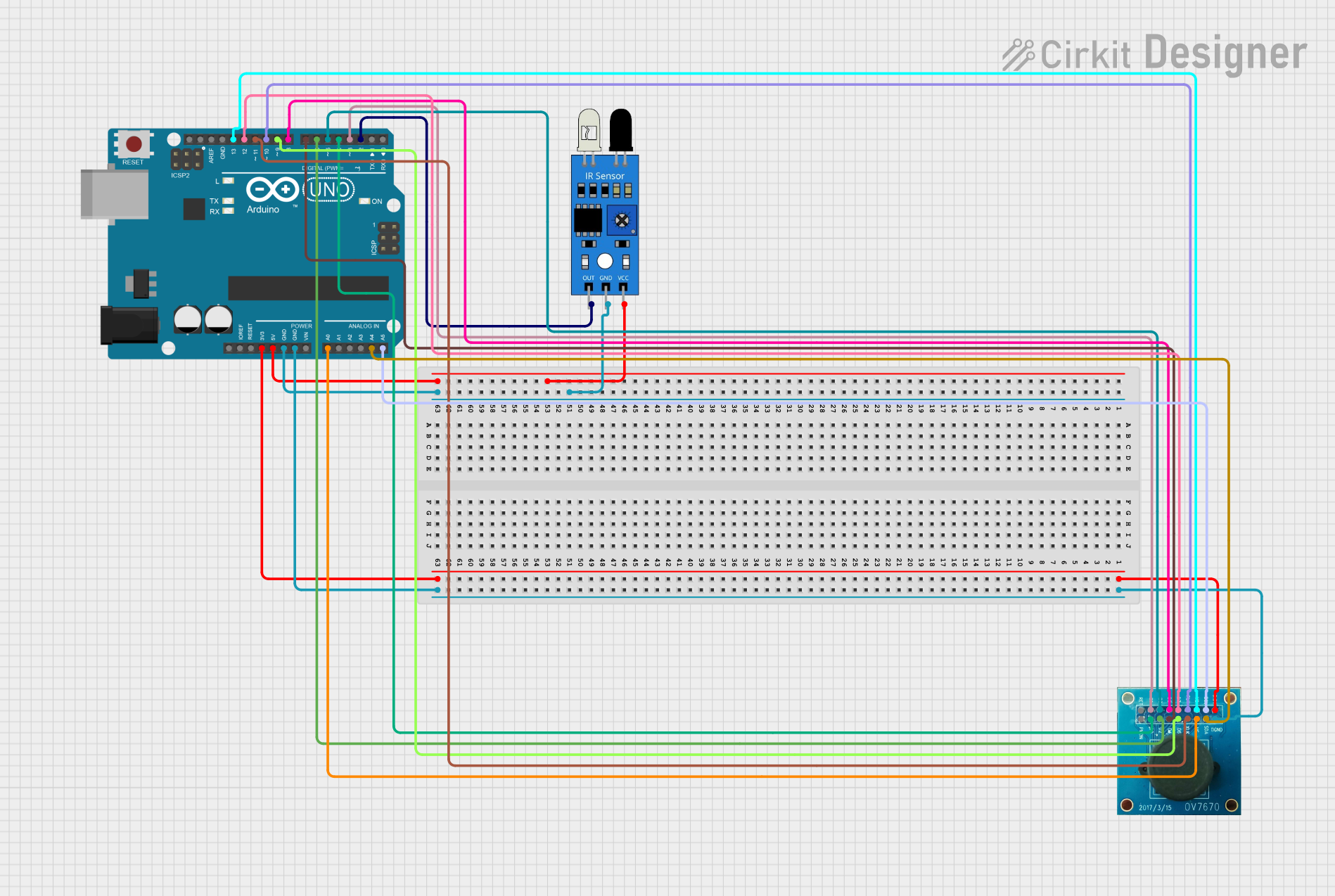
This circuit integrates an Arduino UNO with an OV7670 camera module and an IR sensor. The Arduino is configured to communicate with the OV7670 via digital pins for data transfer and control signals, and with the IR sensor via one of its digital pins to receive detection signals. The camera module and IR sensor are powered by the Arduino's 3.3V and 5V outputs, respectively, and share a common ground.
Explore Projects Built with OPENMV4-CAM-H7
ESP32-CAM Controlled Servo Array with IR Sensing and OLED Feedback
This circuit features an ESP32-CAM microcontroller connected to multiple servo motors and an IR sensor, with a 0.96" OLED display for output. The servos are controlled by the ESP32-CAM via individual IO pins, allowing for independent movement, while the IR sensor's output is also connected to the microcontroller for input sensing. The entire circuit is powered by a 5V adapter, with common ground and power lines for all components.
Arduino UNO-Based Object Detection System with OLED Display and OV7670 Camera Module
This circuit features an Arduino UNO microcontroller interfaced with an OLED display, an OV7670 camera module, and an IR sensor. The Arduino manages image capture from the OV7670 when the IR sensor detects an object, and then displays the image on the OLED screen. The Arduino's digital and analog pins are used to control the camera and communicate with the OLED via I2C, while the IR sensor output is connected to one of the Arduino's digital pins.
Arduino UNO-Based Smart Surveillance System with ArduCam Mega, OV7670, and Wi-Fi Connectivity
This circuit integrates an Arduino UNO with an ArduCam Mega, an OV7670 camera, an HC-SR04 ultrasonic sensor, and a WiFi module ESP8266-01. The system captures images and distance measurements, processes the data, and transmits it over WiFi to a connected device.
Arduino UNO Based IR Object Detection with OV7670 Camera Interface
This circuit integrates an Arduino UNO with an OV7670 camera module and an IR sensor. The Arduino is configured to communicate with the OV7670 via digital pins for data transfer and control signals, and with the IR sensor via one of its digital pins to receive detection signals. The camera module and IR sensor are powered by the Arduino's 3.3V and 5V outputs, respectively, and share a common ground.
Common Applications and Use Cases
- Object detection and tracking
- Face recognition
- QR code and barcode scanning
- Line following robots
- Image filtering and processing
- Edge detection and feature extraction
Technical Specifications
Key Technical Details
| Specification | Value |
|---|---|
| Processor | ARM Cortex-M7 |
| Clock Speed | 480 MHz |
| RAM | 512 KB |
| Flash Memory | 2 MB |
| Camera Sensor | OV7725 (640x480 resolution) |
| Interface | USB, UART, SPI, I2C, CAN, ADC, DAC, PWM |
| Operating Voltage | 3.3V |
| Power Consumption | 140 mA (typical) |
| Dimensions | 45mm x 36mm |
Pin Configuration and Descriptions
| Pin Number | Pin Name | Description |
|---|---|---|
| 1 | GND | Ground |
| 2 | 3.3V | 3.3V Power Supply |
| 3 | P0 | GPIO, ADC, PWM |
| 4 | P1 | GPIO, ADC, PWM |
| 5 | P2 | GPIO, ADC, PWM |
| 6 | P3 | GPIO, ADC, PWM |
| 7 | P4 | GPIO, ADC, PWM |
| 8 | P5 | GPIO, ADC, PWM |
| 9 | P6 | GPIO, ADC, PWM |
| 10 | P7 | GPIO, ADC, PWM |
| 11 | P8 | GPIO, ADC, PWM |
| 12 | P9 | GPIO, ADC, PWM |
| 13 | P10 | GPIO, ADC, PWM |
| 14 | P11 | GPIO, ADC, PWM |
| 15 | P12 | GPIO, ADC, PWM |
| 16 | P13 | GPIO, ADC, PWM |
| 17 | P14 | GPIO, ADC, PWM |
| 18 | P15 | GPIO, ADC, PWM |
| 19 | P16 | GPIO, ADC, PWM |
| 20 | P17 | GPIO, ADC, PWM |
| 21 | P18 | GPIO, ADC, PWM |
| 22 | P19 | GPIO, ADC, PWM |
| 23 | P20 | GPIO, ADC, PWM |
| 24 | P21 | GPIO, ADC, PWM |
| 25 | P22 | GPIO, ADC, PWM |
| 26 | P23 | GPIO, ADC, PWM |
| 27 | P24 | GPIO, ADC, PWM |
| 28 | P25 | GPIO, ADC, PWM |
| 29 | P26 | GPIO, ADC, PWM |
| 30 | P27 | GPIO, ADC, PWM |
| 31 | P28 | GPIO, ADC, PWM |
| 32 | P29 | GPIO, ADC, PWM |
| 33 | P30 | GPIO, ADC, PWM |
| 34 | P31 | GPIO, ADC, PWM |
| 35 | P32 | GPIO, ADC, PWM |
| 36 | P33 | GPIO, ADC, PWM |
| 37 | P34 | GPIO, ADC, PWM |
| 38 | P35 | GPIO, ADC, PWM |
| 39 | P36 | GPIO, ADC, PWM |
| 40 | P37 | GPIO, ADC, PWM |
| 41 | P38 | GPIO, ADC, PWM |
| 42 | P39 | GPIO, ADC, PWM |
| 43 | P40 | GPIO, ADC, PWM |
| 44 | P41 | GPIO, ADC, PWM |
| 45 | P42 | GPIO, ADC, PWM |
| 46 | P43 | GPIO, ADC, PWM |
| 47 | P44 | GPIO, ADC, PWM |
| 48 | P45 | GPIO, ADC, PWM |
| 49 | P46 | GPIO, ADC, PWM |
| 50 | P47 | GPIO, ADC, PWM |
Usage Instructions
How to Use the Component in a Circuit
- Power Supply: Connect the 3.3V pin to a 3.3V power source and the GND pin to ground.
- Communication: Use the USB interface for programming and debugging. For other communication protocols, connect the respective pins (UART, SPI, I2C, CAN).
- Camera: The integrated camera module is ready to use. No additional connections are required.
- GPIO: Use the GPIO pins for interfacing with other sensors, actuators, or modules. Configure them as input or output as needed.
Important Considerations and Best Practices
- Power Supply: Ensure a stable 3.3V power supply to avoid damage to the board.
- Heat Management: The ARM Cortex-M7 processor can get warm during operation. Ensure proper ventilation.
- Firmware Updates: Regularly update the firmware to benefit from the latest features and improvements.
- Static Discharge: Handle the board with care to avoid static discharge, which can damage the components.
Example Code for Arduino UNO
#include <Wire.h>

// Initialize the I2C communication
void setup() {
  Wire.begin(); // Join I2C bus as master
  Serial.begin(9600); // Start serial communication at 9600 baud
}

void loop() {
  Wire.requestFrom(8, 6); // Request 6 bytes from slave device #8

  while (Wire.available()) { // Slave may send less than requested
    char c = Wire.read(); // Receive a byte as character
    Serial.print(c); // Print the character
  }

  delay(500); // Wait for 500 milliseconds
}
Troubleshooting and FAQs
Common Issues Users Might Face
- No Power: Ensure the 3.3V power supply is connected and stable.
- Camera Not Working: Check the firmware and ensure the camera module is properly initialized.
- Communication Failure: Verify the connections and configurations for UART, SPI, I2C, or CAN interfaces.
- Overheating: Ensure proper ventilation and avoid running intensive tasks for prolonged periods.
Solutions and Tips for Troubleshooting
- Check Connections: Ensure all connections are secure and correct.
- Update Firmware: Regularly update the firmware to fix bugs and improve performance.
- Use Proper Libraries: Ensure you are using the correct libraries and drivers for your application.
- Consult Documentation: Refer to the official documentation and community forums for additional support.
By following this documentation, users can effectively utilize the OPENMV4-CAM-H7 for their machine vision projects, ensuring optimal performance and reliability.