How to Use Unbalanced Jack: Examples, Pinouts, and Specs
Introduction
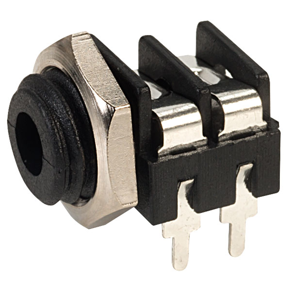
An unbalanced jack, commonly referred to as a mono jack or TS (Tip-Sleeve) jack, is a widely used electrical connector in the audio industry. It is designed for the transmission of mono analog audio signals and is characterized by its simple two-conductor design. The unbalanced jack is a staple in musical instruments like electric guitars, keyboards, and equipment such as amplifiers, mixers, and some headphones.
Explore Projects Built with Unbalanced Jack

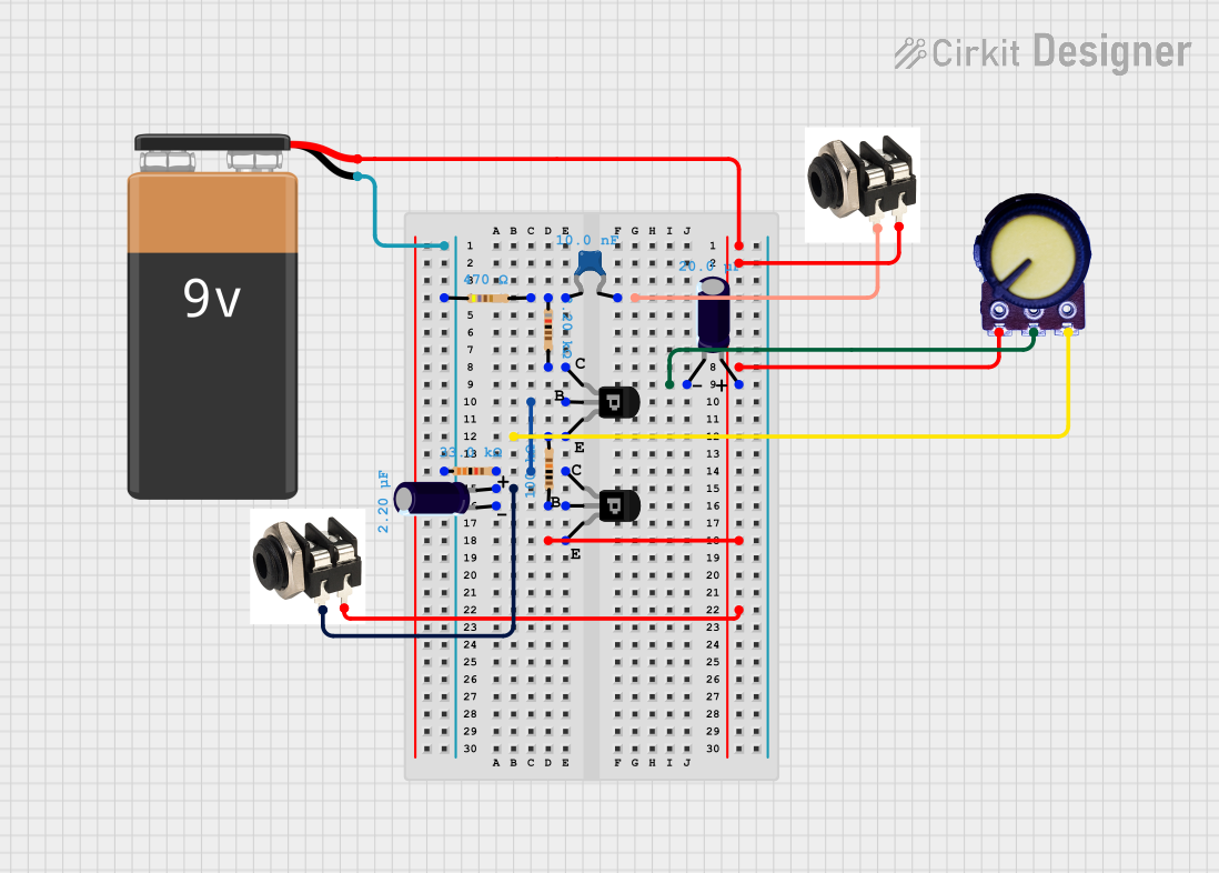


Explore Projects Built with Unbalanced Jack
Common Applications and Use Cases
- Electric guitars and basses
- Keyboards and synthesizers
- Microphones
- Amplifiers and speakers
- Audio interfaces
- Professional and consumer audio equipment
Technical Specifications
Key Technical Details
- Signal Type: Analog Audio (Mono)
- Number of Conductors: 2 (Tip and Sleeve)
- Connection Type: Unbalanced
- Typical Diameter: 6.35mm (1/4 inch) or 3.5mm (1/8 inch)
Pin Configuration and Descriptions
| Pin | Name | Description |
|---|---|---|
| 1 | Tip | Carries the audio signal |
| 2 | Sleeve | Ground connection, completes the circuit |
Usage Instructions
How to Use the Component in a Circuit
Connection: To use an unbalanced jack in a circuit, connect the tip conductor to the signal source (e.g., the output of a guitar pickup) and the sleeve conductor to the common ground.
Soldering: When soldering the jack, ensure that the connections are secure and that there is no short between the tip and sleeve.
Cable Selection: Use a shielded audio cable to minimize interference and noise pickup.
Important Considerations and Best Practices
- Avoiding Ground Loops: Ensure that there is only one ground path between devices to prevent ground loops, which can introduce noise into the audio signal.
- Cable Length: Keep cable lengths as short as possible to reduce the potential for signal degradation and interference.
- Handling: When plugging or unplugging the jack, grasp the connector rather than the cable to avoid stress on the soldered connections.
Troubleshooting and FAQs
Common Issues Users Might Face
- Noise or Hum: This can be caused by poor grounding, interference, or a bad connection. Check the solder joints and the integrity of the cable.
- Intermittent Signal: If the audio cuts in and out, this may indicate a loose connection. Inspect the jack and the cable for any signs of damage or wear.
Solutions and Tips for Troubleshooting
- Re-soldering Connections: If a connection is loose or the solder joint is poor, re-solder the connection for a more stable signal.
- Cable Replacement: If the cable is damaged or worn, replace it with a new one to ensure a clean signal path.
- Contact Cleaner: Use a contact cleaner on the jack to remove any oxidation that may be affecting the connection.
FAQs
Q: Can I use an unbalanced jack for stereo audio? A: No, an unbalanced jack is designed for mono audio. For stereo audio, you would need a TRS (Tip-Ring-Sleeve) jack.
Q: Is there a difference in sound quality between 6.35mm and 3.5mm jacks? A: The diameter of the jack itself does not affect sound quality. However, the build quality and shielding of the cable can influence the audio signal.
Q: How can I tell if my jack is unbalanced? A: An unbalanced jack will have two conductive areas separated by an insulating ring, corresponding to the tip and sleeve.
Example Code for Arduino UNO
The following is an example of how to use an unbalanced jack with an Arduino UNO to read an analog audio signal. This setup could be used for simple audio signal processing or visualization.
// Define the analog input pin where the unbalanced jack's tip is connected.
const int audioInputPin = A0;

void setup() {
  // Initialize serial communication at 9600 bits per second:
  Serial.begin(9600);
}

void loop() {
  // Read the voltage on the audio input pin:
  int sensorValue = analogRead(audioInputPin);

  // Print out the value to the Serial Monitor:
  Serial.println(sensorValue);

  // Wait for 10 milliseconds for the next read (adjust as needed):
  delay(10);
}
Note: This code is for demonstration purposes and does not include audio signal processing. It simply reads the analog voltage level from the unbalanced jack and outputs it to the Serial Monitor.