How to Use AMS1117: Examples, Pinouts, and Specs
AMS1117 Linear Voltage Regulator Documentation
Introduction
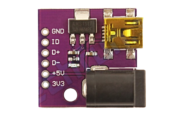
The AMS1117 is a low dropout (LDO) linear voltage regulator designed to provide a stable and regulated output voltage for electronic circuits. Manufactured by Techfun with the part ID ZDR759, this component is capable of delivering a maximum output current of 1A. It is widely used in power supply circuits to step down and regulate voltage levels for microcontrollers, sensors, and other electronic devices.
Common Applications
- Voltage regulation for microcontrollers (e.g., Arduino, ESP8266, Raspberry Pi)
- Power supply for sensors and modules
- Battery-powered devices
- DC-DC step-down voltage regulation
- General-purpose voltage regulation in embedded systems
Technical Specifications
The AMS1117 is available in multiple fixed output voltage variants (e.g., 1.2V, 1.5V, 1.8V, 2.5V, 3.3V, 5V) and an adjustable version. Below are the key technical details:
Key Specifications
| Parameter | Value |
|---|---|
| Input Voltage Range | 4.6V to 15V |
| Output Voltage Options | 1.2V, 1.5V, 1.8V, 2.5V, 3.3V, 5V |
| Adjustable Output Voltage | 1.25V to 13.8V (for adjustable version) |
| Maximum Output Current | 1A |
| Dropout Voltage | 1.1V (at 1A load) |
| Quiescent Current | 5mA (typical) |
| Operating Temperature Range | -40°C to +125°C |
| Package Type | SOT-223, TO-252 |
Pin Configuration
The AMS1117 has three pins, as shown in the table below:
| Pin Number | Pin Name | Description |
|---|---|---|
| 1 | ADJ/GND | Ground (for fixed versions) or Adjust (for adjustable version) |
| 2 | VOUT | Regulated output voltage |
| 3 | VIN | Input voltage |
Usage Instructions
How to Use the AMS1117 in a Circuit
- Input Voltage: Connect the input voltage (VIN) to the VIN pin. Ensure the input voltage is at least 1.1V higher than the desired output voltage (dropout voltage).
- Output Voltage: The regulated output voltage is available at the VOUT pin. For fixed versions, this voltage is pre-set (e.g., 3.3V or 5V). For the adjustable version, use an external resistor divider to set the desired output voltage.
- Ground Connection: Connect the ADJ/GND pin to ground for fixed versions. For the adjustable version, connect it to the resistor divider network.
- Capacitors: Use input and output capacitors for stability:
- Input Capacitor: A 10µF capacitor is recommended between VIN and GND.
- Output Capacitor: A 10µF capacitor is recommended between VOUT and GND.
Example Circuit
Below is an example of using the AMS1117-3.3V to regulate a 5V input to a 3.3V output:
   +5V Input
      |
      |
     [10µF]  <-- Input Capacitor
      |
      |----> VIN (Pin 3)
      |
   AMS1117-3.3V
      |
      |----> VOUT (Pin 2) ----> +3.3V Output
      |
     [10µF]  <-- Output Capacitor
      |
     GND (Pin 1)
Important Considerations
- Thermal Management: The AMS1117 can dissipate significant heat at high currents. Use a heatsink or ensure proper PCB thermal design to avoid overheating.
- Dropout Voltage: Ensure the input voltage is at least 1.1V higher than the desired output voltage.
- Capacitor Selection: Use low ESR capacitors for better stability and performance.
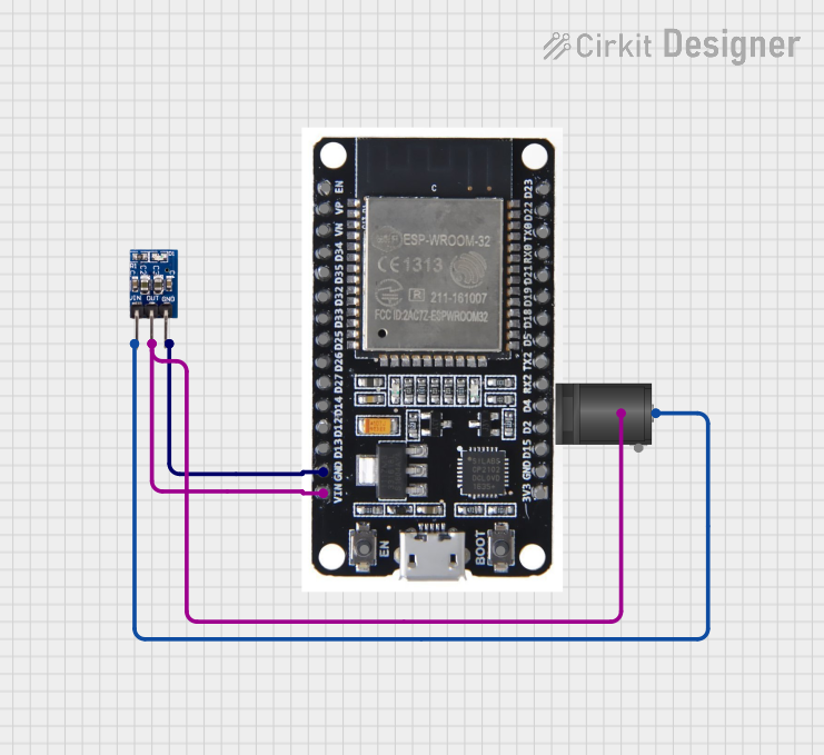
Arduino Example
The AMS1117-3.3V is commonly used to power 3.3V devices like ESP8266 modules. Below is an example of connecting the AMS1117 to an Arduino UNO to power an ESP8266:
Circuit Diagram
Connect the AMS1117 as follows:
- VIN: Connect to the Arduino's 5V pin.
- VOUT: Connect to the ESP8266's VCC pin.
- GND: Connect to the Arduino's GND pin.
Add capacitors:
- Place a 10µF capacitor between VIN and GND.
- Place a 10µF capacitor between VOUT and GND.
Arduino Code
Here is an example code to communicate with the ESP8266 powered by the AMS1117:
#include <SoftwareSerial.h>

// Define RX and TX pins for SoftwareSerial
SoftwareSerial esp8266(2, 3); // RX = Pin 2, TX = Pin 3

void setup() {
  // Initialize serial communication
  Serial.begin(9600); // Communication with PC
  esp8266.begin(115200); // Communication with ESP8266

  Serial.println("Initializing ESP8266...");
  esp8266.println("AT"); // Send AT command to test communication
}

void loop() {
  // Check if data is available from ESP8266
  if (esp8266.available()) {
    String response = esp8266.readString();
    Serial.println("ESP8266 Response: " + response);
  }

  // Check if data is available from Serial Monitor
  if (Serial.available()) {
    String command = Serial.readString();
    esp8266.println(command); // Send command to ESP8266
  }
}
Troubleshooting and FAQs
Common Issues
No Output Voltage
- Cause: Input voltage is too low.
- Solution: Ensure the input voltage is at least 1.1V higher than the desired output voltage.
Overheating
- Cause: Excessive current draw or insufficient heat dissipation.
- Solution: Use a heatsink or improve PCB thermal design. Reduce the load current if possible.
Unstable Output Voltage
- Cause: Missing or incorrect capacitors.
- Solution: Add a 10µF capacitor to both the input and output pins.
Output Voltage Too Low
- Cause: Incorrect resistor divider (for adjustable version).
- Solution: Verify the resistor values and connections.
FAQs
Can I use the AMS1117 to power a 3.3V microcontroller from a 5V source?
- Yes, the AMS1117-3.3V is ideal for this purpose. Ensure proper capacitors are used.
What is the maximum current the AMS1117 can handle?
- The AMS1117 can handle up to 1A, but thermal management is critical at high currents.
Can I use the AMS1117 without capacitors?
- No, capacitors are essential for stability and proper operation.
What is the difference between the fixed and adjustable versions?
- Fixed versions provide a pre-set output voltage (e.g., 3.3V), while the adjustable version allows you to set the output voltage using external resistors.
Conclusion
The AMS1117 is a versatile and reliable voltage regulator suitable for a wide range of applications. By following the guidelines in this documentation, you can effectively integrate the AMS1117 into your projects for stable and efficient voltage regulation. For further assistance, refer to the manufacturer's datasheet or contact Techfun support.
Explore Projects Built with AMS1117


Explore Projects Built with AMS1117