The CC3000 WiFi Breakout Board is a compact wireless network module that enables internet connectivity for microcontroller-based projects. By integrating this module, devices can connect to Wi-Fi networks and communicate with the internet or other networked devices. Common applications include home automation, IoT devices, and wireless sensor networks.
Explore Projects Built with CC3000 WiFi Breakout Board
Use Cirkit Designer to design, explore, and prototype these projects online. Some projects support real-time simulation. Click "Open Project" to start designing instantly!
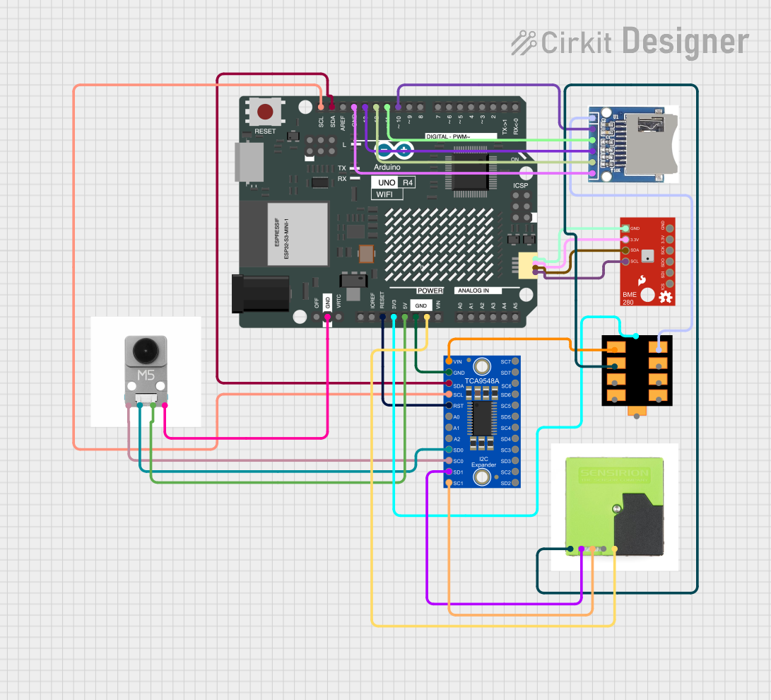
This circuit features an Arduino UNO R4 WiFi as the central microcontroller, interfaced with a BME280 Breakout sensor for environmental data, an SD card module for data logging, and a TCA9548A I2C multiplexer to manage multiple I2C devices. It also includes a U078-V-M12 sensor and an SPS30 particulate matter sensor, both connected through the I2C multiplexer. Power distribution is managed by a dedicated board that receives 3.3V from the Arduino and distributes it to the SD card module and other components.
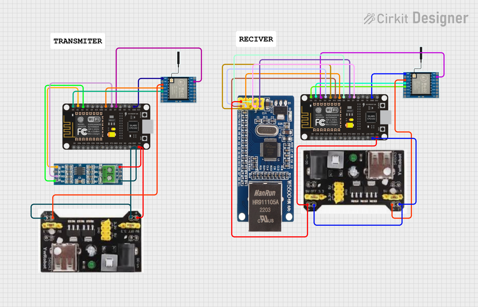
This circuit serves as a multi-protocol communication hub featuring two ESP8266 NodeMCUs for processing, each connected to a LoRa Ra-02 SX1278 for long-range wireless communication. One NodeMCU is also connected to an RS-485 module for serial communication and a W5500 Ethernet module for network connectivity, with MB102 modules supplying power.
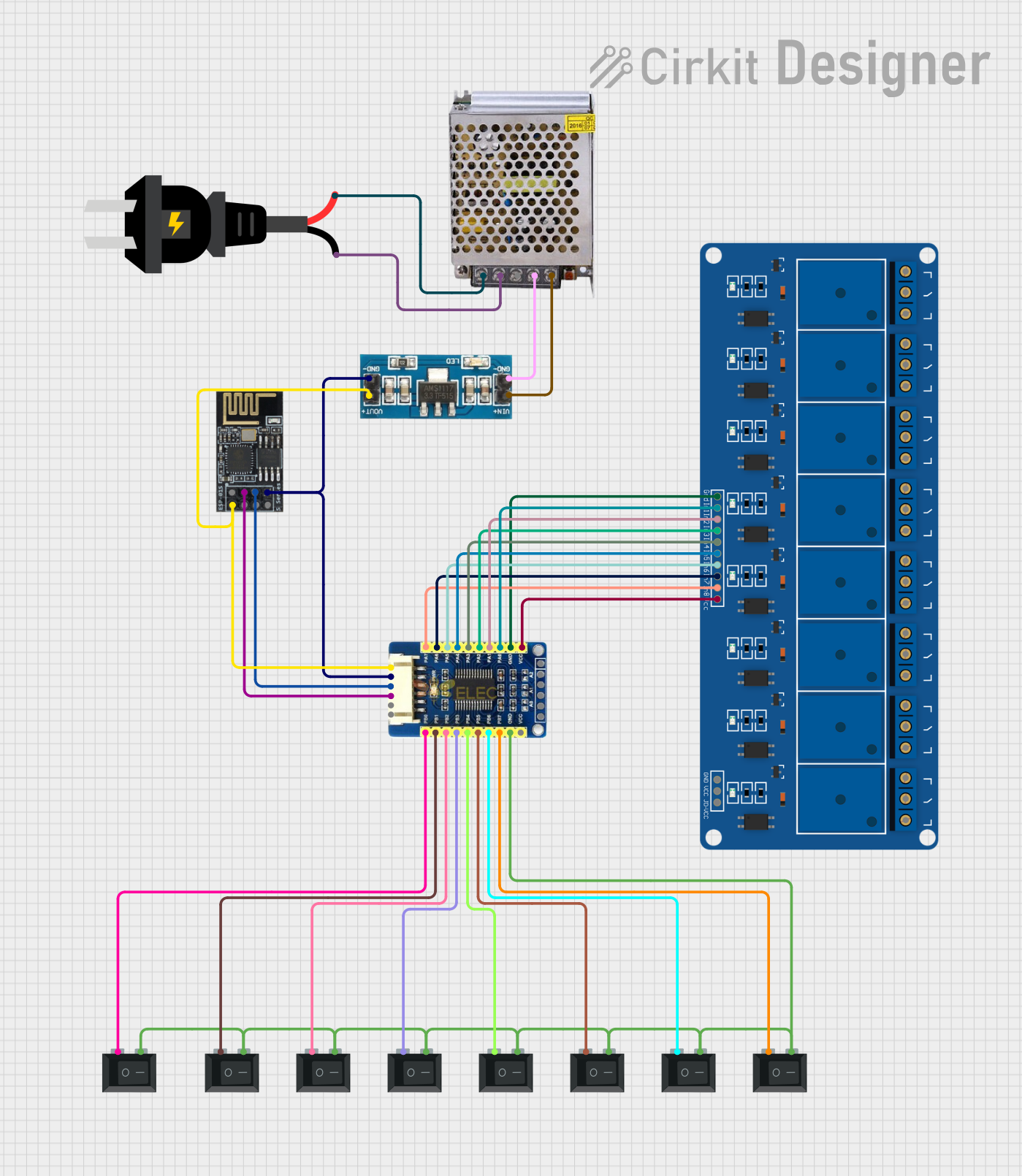
This circuit is a WiFi-enabled relay control system using an ESP8266-01 module and an MCP23017 I/O expander. The ESP8266 communicates with the MCP23017 via I2C to control an 8-channel relay module based on the state of 8 rocker switches, allowing for remote and manual control of connected devices.
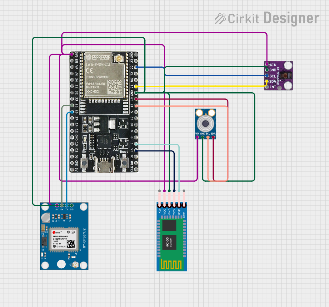
This circuit features an ESP32-WROOM-32UE microcontroller as the central processing unit, interfacing with a variety of sensors and modules. It includes a MAX30100 pulse oximeter and heart-rate sensor, an MLX90614 infrared thermometer, an HC-05 Bluetooth module for wireless communication, and a Neo 6M GPS module for location tracking. All components are powered by a common voltage supply and are connected to specific GPIO pins on the ESP32 for data exchange, with the sensors using I2C communication and the modules using UART.
Current Consumption: ~92 mA during transmission, ~0.6 mA in standby
Frequency Range: 2.4 GHz ISM band
Antenna: Integrated PCB antenna or U.FL connector for external antenna
Dimensions: Typically around 26mm x 39mm (size may vary slightly by manufacturer)
Pin Configuration and Descriptions
Pin Number
Name
Description
1
VBAT
Power supply (3.0V-3.6V)
2
GND
Ground connection
3
EN
Enable pin (active high)
4
IRQ
Interrupt request, active low
5
SPI_MOSI
SPI data input to CC3000
6
SPI_MISO
SPI data output from CC3000
7
SPI_CLK
SPI clock signal
8
SPI_CS
SPI chip select, active low
Usage Instructions
Integration with a Circuit
Power Supply: Connect the VBAT pin to a 3.3V supply and GND to the ground.
SPI Interface: Connect the SPI pins (MOSI, MISO, CLK, CS) to the corresponding SPI pins on the microcontroller.
Enable and Interrupt: Connect the EN pin to a digital output for module enable/disable control and the IRQ pin to an interrupt-capable pin on the microcontroller.
Best Practices
Ensure that the power supply is stable and within the specified voltage range.
Use a level shifter if interfacing with a 5V microcontroller to protect the CC3000's 3.3V logic.
Place the board away from noise sources and metal objects to minimize interference with the Wi-Fi signal.
Update the CC3000 firmware to the latest version to ensure compatibility and security.
Example Code for Arduino UNO
#include <Adafruit_CC3000.h>
#include <ccspi.h>
#include <SPI.h>

// Define the pins for the CC3000 chip
#define ADAFRUIT_CC3000_IRQ   3
#define ADAFRUIT_CC3000_VBAT  5
#define ADAFRUIT_CC3000_CS    10

// Create an instance of the library
Adafruit_CC3000 cc3000 = Adafruit_CC3000(ADAFRUIT_CC3000_CS, ADAFRUIT_CC3000_IRQ, ADAFRUIT_CC3000_VBAT, SPI_CLOCK_DIVIDER);

void setup() {
  Serial.begin(115200);
  Serial.println(F("CC3000 WiFi module starting"));

  // Initialize the CC3000 (SPI clock speed should be adjusted as necessary)
  if (!cc3000.begin()) {
    Serial.println(F("Unable to initialize the CC3000! Check your wiring?"));
    while(1);
  }

  // Attempt to connect to an open Wi-Fi network
  if (!cc3000.connectToAP("SSID", "PASSWORD", WLAN_SEC_WPA2)) {
    Serial.println(F("Failed to connect to WiFi network."));
    while(1);
  }

  Serial.println(F("Connected!"));

  // ... Additional code to use network features ...
}

void loop() {
  // Main loop code goes here
}
Note: Replace "SSID" and "PASSWORD" with your Wi-Fi network's SSID and password. The security type WLAN_SEC_WPA2 should be adjusted according to your network's security settings.
Troubleshooting and FAQs
Common Issues
Module Does Not Power On: Check the power supply and connections to the VBAT and GND pins.
Cannot Connect to Wi-Fi: Ensure the SSID and password are correct. Verify that the Wi-Fi network is within range and operating on the 2.4 GHz band.
Intermittent Connectivity: Check for sources of electromagnetic interference near the module or consider using an external antenna if the signal strength is weak.
FAQs
Q: Can the CC3000 be used with a 5V microcontroller?
A: Yes, but a level shifter is required to convert the 5V signals to 3.3V to avoid damaging the CC3000.
Q: How do I update the firmware on the CC3000?
A: Firmware updates can be performed using a special firmware update sketch provided by the manufacturer or community. Follow the instructions carefully to avoid bricking the module.
Q: What is the maximum range of the CC3000?
A: The range depends on many factors, including the environment and antenna used. Typically, it can range from 50 to 100 meters indoors.
For further assistance, consult the manufacturer's datasheet and user forums for additional resources and community support.


 Open Project in Cirkit Designer