How to Use 24V Power Cord: Examples, Pinouts, and Specs
Introduction
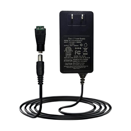
A 24V power cord is a cable designed to connect electrical devices to a 24-volt power supply, providing the necessary voltage for operation. These cords are essential for powering a wide range of devices, including industrial equipment, LED lighting systems, and certain types of motors. They ensure a stable and reliable connection between the power source and the device, making them a critical component in many electrical systems.
Explore Projects Built with 24V Power Cord


Explore Projects Built with 24V Power Cord
Common Applications and Use Cases
- Powering industrial machinery and automation systems
- Supplying power to 24V LED lighting strips and fixtures
- Connecting 24V DC motors in robotics and automotive applications
- Providing power to communication equipment and networking devices
- Used in renewable energy systems, such as solar panel setups
Technical Specifications
Below are the key technical details of a standard 24V power cord:
| Specification | Details |
|---|---|
| Voltage Rating | 24V DC |
| Current Rating | Typically 5A to 10A (varies by cord type and gauge) |
| Power Rating | Up to 240W (depending on current rating) |
| Wire Gauge | Commonly 18 AWG to 14 AWG (thicker wires for higher current capacity) |
| Connector Type | Barrel jack, spade terminals, or bare wire ends (varies by application) |
| Insulation Material | PVC or rubber (for durability and electrical safety) |
| Length | Typically 1m to 3m (custom lengths available) |
| Operating Temperature | -20°C to 70°C (varies by insulation material) |
| Certifications | UL, CE, or RoHS compliance (varies by manufacturer) |
Pin Configuration and Descriptions
For a 24V power cord with a standard barrel connector, the pin configuration is as follows:
| Pin | Description |
|---|---|
| Outer Sleeve | Ground (negative terminal) |
| Inner Pin | Positive terminal (24V DC supply) |
For cords with bare wire ends:
- Red Wire: Positive terminal (24V DC supply)
- Black Wire: Ground (negative terminal)
Usage Instructions
How to Use the 24V Power Cord in a Circuit
- Verify Compatibility: Ensure the device you are powering is designed to operate at 24V DC and does not exceed the current rating of the power cord.
- Inspect the Cord: Check the cord for any visible damage, such as frayed wires or exposed conductors, before use.
- Connect to Power Supply:
- For barrel connectors: Insert the connector into the device's power input port, ensuring a snug fit.
- For bare wire ends: Connect the red wire to the positive terminal and the black wire to the negative terminal of the power supply.
- Secure Connections: If using bare wire ends, tighten the connections with screws or terminal blocks to prevent loose connections.
- Power On: Turn on the power supply and verify that the connected device operates as expected.
Important Considerations and Best Practices
- Polarity: Always double-check the polarity of the connections to avoid damaging the device.
- Current Rating: Ensure the power cord's current rating matches or exceeds the device's requirements.
- Cable Management: Use cable ties or clips to secure the cord and prevent tripping hazards or accidental disconnections.
- Environmental Conditions: Avoid exposing the cord to extreme temperatures, moisture, or chemicals that could degrade the insulation.
Example: Connecting a 24V Power Cord to an Arduino UNO
While the Arduino UNO typically operates at 5V, you can use a 24V power cord with a step-down voltage regulator to safely power the board. Below is an example circuit and code:
Circuit Setup
- Connect the 24V power cord to a DC-DC step-down converter (e.g., LM2596).
- Adjust the converter output to 5V using a multimeter.
- Connect the converter's output to the Arduino UNO's VIN and GND pins.
Example Code
// Example code to blink an LED connected to pin 13 on the Arduino UNO
// Ensure the step-down converter provides a stable 5V to the Arduino

void setup() {
  pinMode(13, OUTPUT); // Set pin 13 as an output pin
}

void loop() {
  digitalWrite(13, HIGH); // Turn the LED on
  delay(1000);            // Wait for 1 second
  digitalWrite(13, LOW);  // Turn the LED off
  delay(1000);            // Wait for 1 second
}
Troubleshooting and FAQs
Common Issues Users Might Face
Device Not Powering On:
- Cause: Incorrect polarity or loose connections.
- Solution: Verify the polarity and ensure all connections are secure.
Overheating of the Cord:
- Cause: Exceeding the current rating of the cord.
- Solution: Use a cord with a higher current rating or reduce the load on the circuit.
Intermittent Power Loss:
- Cause: Damaged insulation or frayed wires.
- Solution: Replace the power cord immediately to avoid safety hazards.
Voltage Drop:
- Cause: Excessive cord length or insufficient wire gauge.
- Solution: Use a shorter cord or one with a thicker wire gauge.
Solutions and Tips for Troubleshooting
- Use a multimeter to check the voltage at the device's input terminals.
- Inspect the cord for physical damage or wear and replace it if necessary.
- Ensure the power supply is functioning correctly and providing a stable 24V output.
By following this documentation, you can safely and effectively use a 24V power cord in your projects and applications.