How to Use Motoron M2T256: Examples, Pinouts, and Specs
Introduction
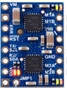
The Motoron M2T256, manufactured by Pololu, is a dual-channel motor controller designed for driving DC motors and stepper motors. It features a built-in microcontroller that allows for easy control via I2C or UART interfaces. With its ability to handle up to 2A per channel, the M2T256 is ideal for applications requiring precise speed and direction control, such as robotics, automation systems, and small-scale industrial machinery.
Explore Projects Built with Motoron M2T256
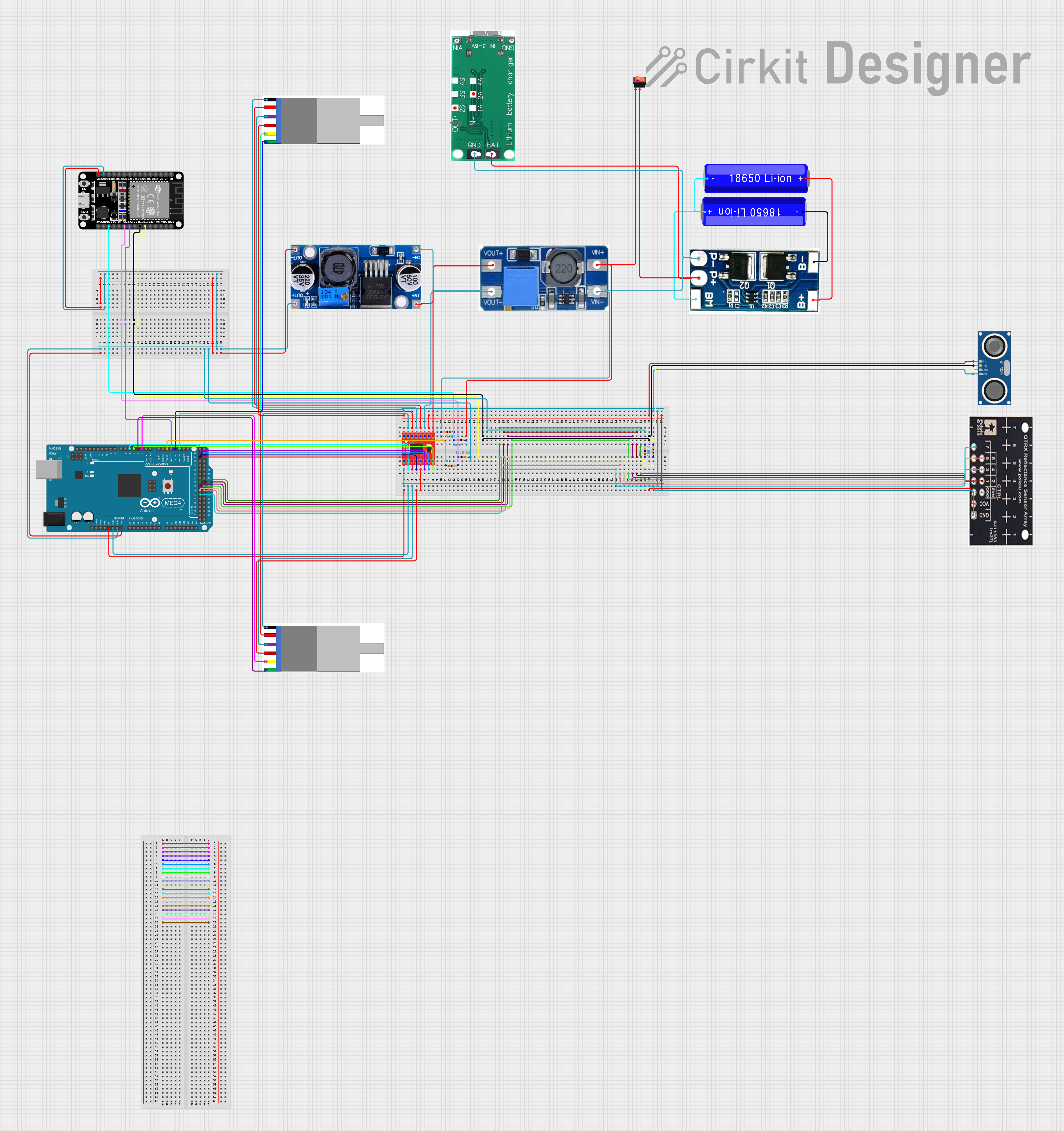
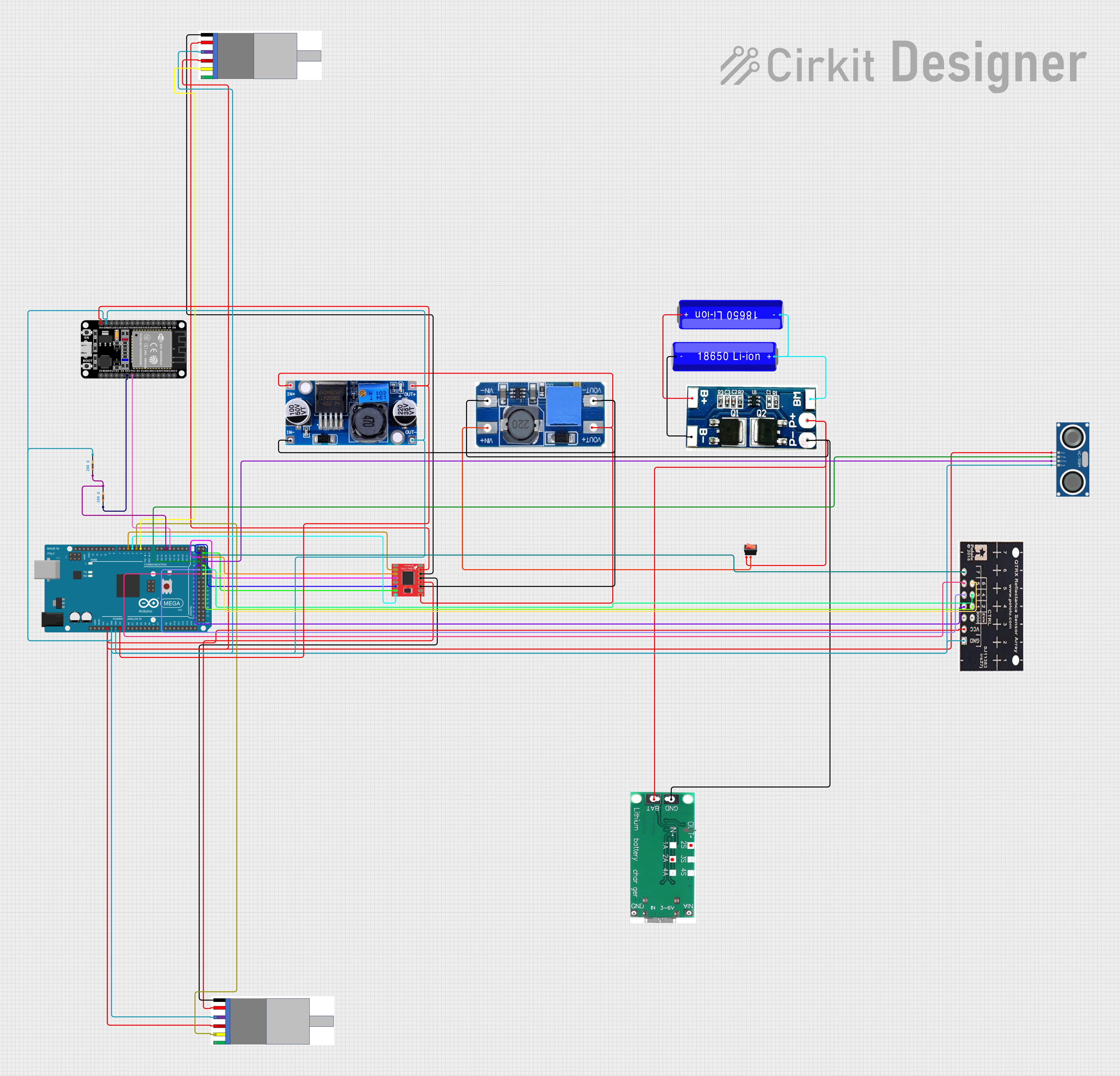
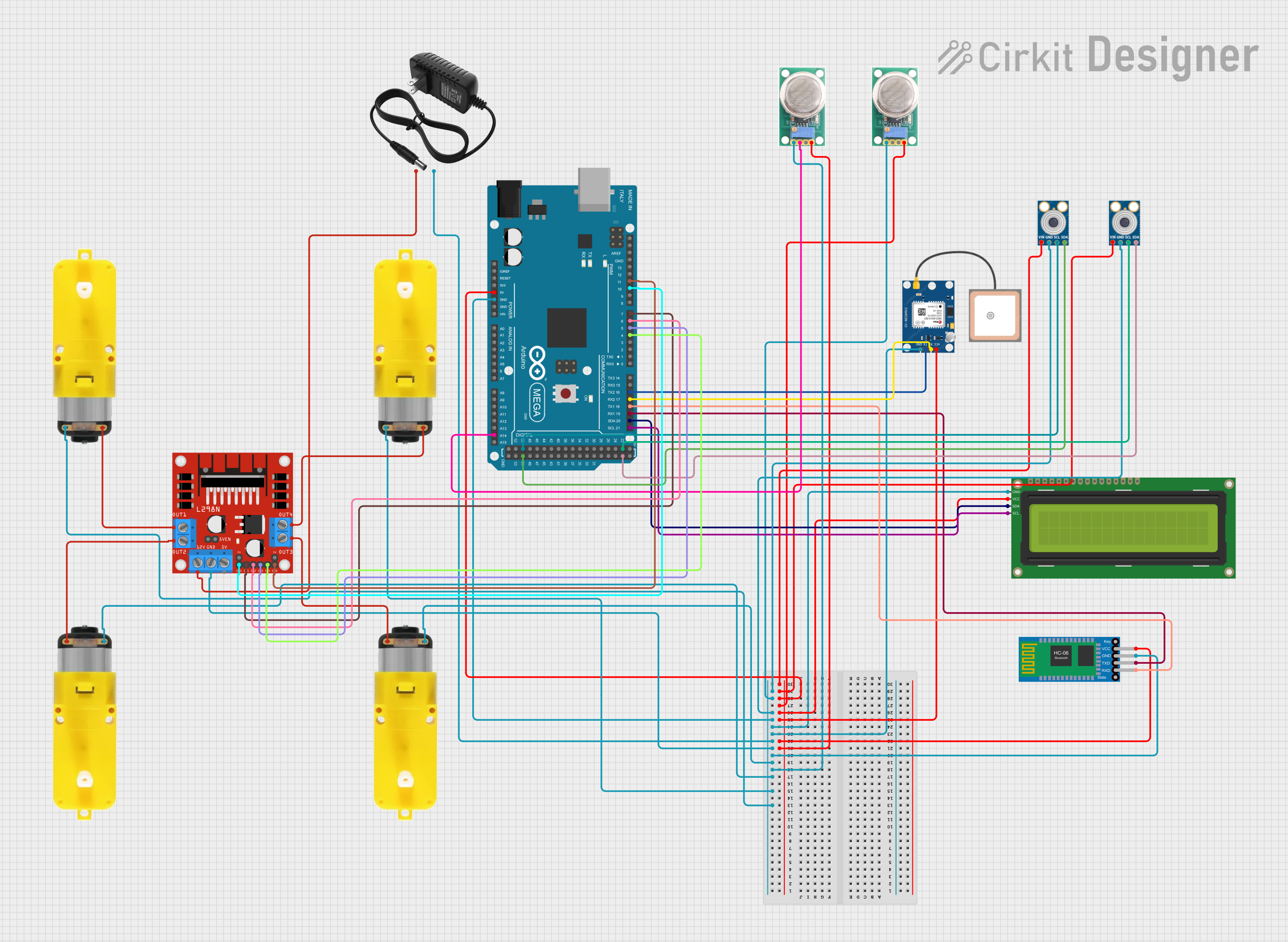
Explore Projects Built with Motoron M2T256
Common Applications
- Robotics (e.g., mobile robots, robotic arms)
- Conveyor belt systems
- Automated guided vehicles (AGVs)
- Stepper motor-based positioning systems
- Educational and hobbyist projects
Technical Specifications
Key Specifications
| Parameter | Value |
|---|---|
| Operating Voltage Range | 4.5V to 48V |
| Maximum Continuous Current (per channel) | 2A |
| Communication Interfaces | I2C, UART |
| Motor Channels | 2 |
| Control Modes | Speed, direction, step/dir |
| PWM Frequency | Up to 20 kHz |
| Logic Voltage | 3.3V or 5V (compatible) |
| Dimensions | 1.0" × 1.2" × 0.2" (approx.) |
| Weight | 2.5 g |
Pin Configuration and Descriptions
The Motoron M2T256 has a compact pin layout for easy integration into your circuit. Below is the pin configuration:
| Pin Name | Pin Type | Description |
|---|---|---|
| VIN | Power Input | Main power supply for the motors (4.5V to 48V). |
| GND | Power Ground | Ground connection for the power supply and logic. |
| SDA | I2C Data | Data line for I2C communication. |
| SCL | I2C Clock | Clock line for I2C communication. |
| TX | UART Output | UART transmit pin for serial communication. |
| RX | UART Input | UART receive pin for serial communication. |
| M1A | Motor Output | Motor 1 output terminal A. |
| M1B | Motor Output | Motor 1 output terminal B. |
| M2A | Motor Output | Motor 2 output terminal A. |
| M2B | Motor Output | Motor 2 output terminal B. |
| RESET | Input | Active-low reset pin to restart the controller. |
| CONFIG | Input | Configuration pin for setting the I2C address or other parameters. |
Usage Instructions
Using the Motoron M2T256 in a Circuit
- Power Supply: Connect the VIN pin to a power source within the range of 4.5V to 48V. Ensure the power supply can provide sufficient current for your motors.
- Motor Connections: Connect the motors to the M1A/M1B and M2A/M2B pins. Ensure the motors' current ratings do not exceed 2A per channel.
- Communication Interface:
- For I2C: Connect the SDA and SCL pins to the corresponding pins on your microcontroller.
- For UART: Connect the TX and RX pins to the UART pins on your microcontroller.
- Logic Voltage: Ensure the logic voltage levels of your microcontroller are compatible with the M2T256 (3.3V or 5V).
- Optional Pins: Use the RESET pin to restart the controller if needed. The CONFIG pin can be used to set the I2C address or other parameters.
Important Considerations
- Heat Dissipation: The M2T256 can handle up to 2A per channel, but prolonged operation at high currents may cause overheating. Use proper heat management techniques, such as adding a heatsink or ensuring adequate airflow.
- Motor Voltage: Ensure the motor voltage matches the power supply voltage to avoid damage.
- I2C Address: If using multiple M2T256 controllers on the same I2C bus, configure unique I2C addresses using the CONFIG pin.
Example: Controlling the M2T256 with an Arduino UNO (I2C)
Below is an example Arduino sketch to control the Motoron M2T256 via I2C:
#include <Wire.h> // Include the Wire library for I2C communication

#define MOTORON_I2C_ADDRESS 0x10 // Default I2C address of the M2T256

void setup() {
  Wire.begin(); // Initialize I2C communication
  Serial.begin(9600); // Initialize serial communication for debugging

  // Set motor 1 speed to 50% forward
  setMotorSpeed(1, 50);

  // Set motor 2 speed to 25% reverse
  setMotorSpeed(2, -25);
}

void loop() {
  // Add your main code here
}

// Function to set motor speed
void setMotorSpeed(uint8_t motor, int8_t speed) {
  Wire.beginTransmission(MOTORON_I2C_ADDRESS); // Start I2C communication
  Wire.write(0x01); // Command to set motor speed
  Wire.write(motor); // Motor number (1 or 2)
  Wire.write(speed); // Speed (-100 to 100, where negative is reverse)
  Wire.endTransmission(); // End I2C communication
}
Best Practices
- Always double-check your wiring before powering the circuit.
- Use decoupling capacitors near the VIN pin to reduce noise.
- Avoid exceeding the maximum current and voltage ratings to prevent damage.
Troubleshooting and FAQs
Common Issues and Solutions
| Issue | Possible Cause | Solution |
|---|---|---|
| Motors not spinning | Incorrect wiring or loose connections | Verify all connections, especially motor and power supply connections. |
| Overheating of the controller | Exceeding current limits | Reduce motor load or add a heatsink for better heat dissipation. |
| I2C communication not working | Incorrect I2C address or wiring | Check the I2C address and ensure SDA/SCL are correctly connected. |
| UART communication issues | Baud rate mismatch | Ensure the baud rate matches between the M2T256 and the microcontroller. |
| Motors spinning in the wrong direction | Reversed motor connections | Swap the M1A/M1B or M2A/M2B connections to reverse the direction. |
FAQs
Can the M2T256 control stepper motors? Yes, the M2T256 supports stepper motor control in step/dir mode.
What happens if I exceed the current limit? The M2T256 has built-in overcurrent protection, but prolonged overcurrent conditions may cause overheating or damage.
Can I use the M2T256 with a Raspberry Pi? Yes, the M2T256 can be controlled via I2C or UART, both of which are supported by the Raspberry Pi.
How do I change the I2C address? Use the CONFIG pin to set a new I2C address. Refer to the Pololu documentation for detailed instructions.
By following this documentation, you can effectively integrate the Motoron M2T256 into your projects and troubleshoot common issues with ease.