How to Use 3.7V Battery: Examples, Pinouts, and Specs
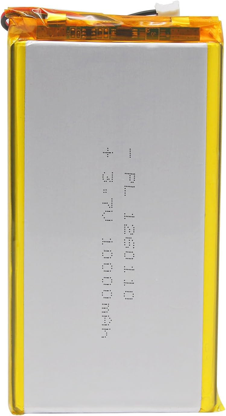
Qimoo 3.7V Rechargeable Lithium-Ion Battery Documentation
1. Introduction
The Qimoo 3.7V Rechargeable Lithium-Ion Battery is a compact and efficient power source designed for a wide range of portable electronic devices. With a nominal voltage of 3.7V, this battery is ideal for applications requiring lightweight, rechargeable, and long-lasting energy storage. It is commonly used in devices such as:
- Wearable electronics (e.g., smartwatches, fitness trackers)
- Portable gadgets (e.g., Bluetooth speakers, handheld gaming devices)
- DIY electronics projects (e.g., Arduino-based systems, IoT devices)
- Drones and RC vehicles
This battery is known for its high energy density, low self-discharge rate, and ability to deliver consistent power over extended periods.
2. Technical Specifications
The following table outlines the key technical details of the Qimoo 3.7V battery:
| Parameter | Specification |
|---|---|
| Nominal Voltage | 3.7V |
| Capacity Range | 500mAh to 3000mAh (varies by model) |
| Chemistry | Lithium-Ion |
| Charging Voltage | 4.2V (maximum) |
| Discharge Cutoff Voltage | 3.0V |
| Maximum Discharge Current | 1C to 3C (varies by model) |
| Charging Current | Standard: 0.5C, Maximum: 1C |
| Operating Temperature | Charge: 0°C to 45°C, Discharge: -20°C to 60°C |
| Dimensions | Varies by capacity (e.g., 18650 form factor) |
| Weight | Varies by capacity |
Pin Configuration and Descriptions
The Qimoo 3.7V battery typically has two terminals:
| Pin | Name | Description |
|---|---|---|
| + | Positive | Positive terminal for power output |
| - | Negative | Negative terminal for power output (ground) |
3. Usage Instructions
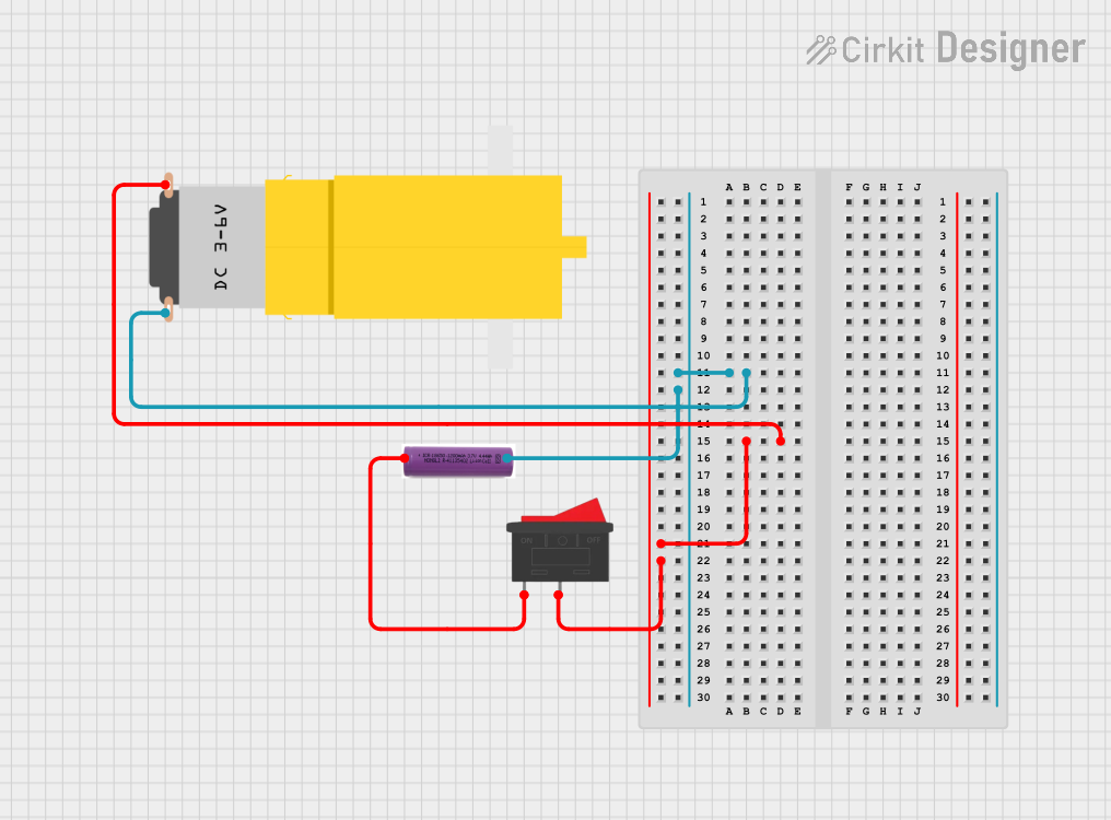
Connecting the Battery to a Circuit
- Identify the Terminals: Locate the positive (+) and negative (-) terminals on the battery.
- Connect to Load: Use appropriate wires to connect the battery terminals to the circuit. Ensure correct polarity to avoid damage.
- Charging the Battery:
- Use a compatible lithium-ion battery charger with a maximum charging voltage of 4.2V.
- Set the charging current to 0.5C (e.g., for a 1000mAh battery, use a 500mA charging current).
- Monitor Voltage: Avoid over-discharging the battery below 3.0V to prevent damage.
Important Considerations and Best Practices
- Safety First: Never short-circuit the terminals, puncture, or expose the battery to fire.
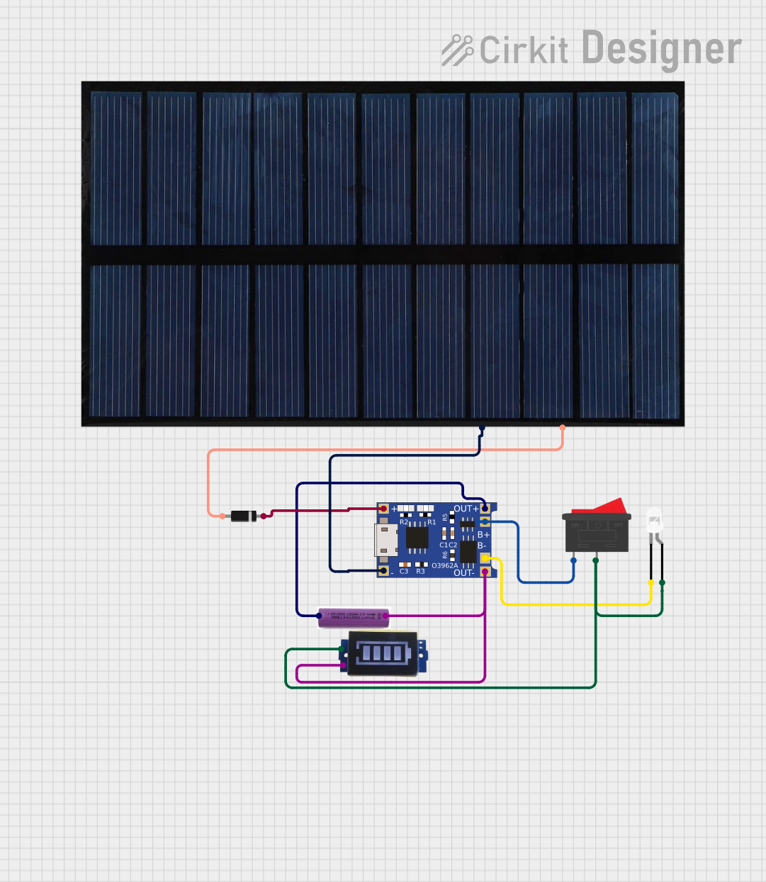
- Use a Protection Circuit: For added safety, use a battery protection circuit module (PCM) to prevent overcharging, over-discharging, and short circuits.
- Storage: Store the battery in a cool, dry place at a charge level of 40-60% for long-term storage.
- Avoid Overcharging: Disconnect the battery from the charger once it reaches 4.2V.
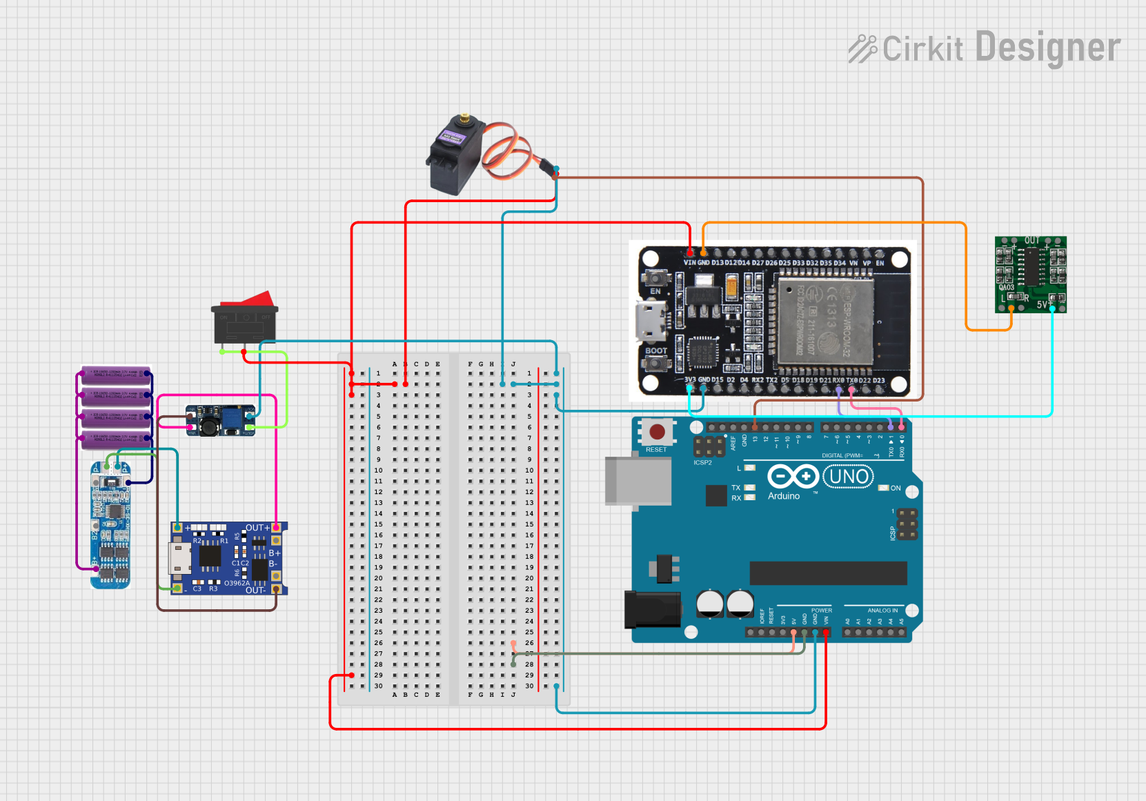
4. Example Application with Arduino UNO
The Qimoo 3.7V battery can be used to power an Arduino UNO via a DC-DC boost converter to step up the voltage to 5V. Below is an example of how to connect and use the battery in a simple LED blinking project.
Circuit Diagram
- Connect the battery to the input of a DC-DC boost converter.
- Set the output of the boost converter to 5V.
- Connect the output of the boost converter to the Arduino UNO's VIN and GND pins.
Arduino Code Example
// Simple LED Blinking Example
// This code blinks an LED connected to pin 13 of the Arduino UNO.
// Ensure the battery is connected to the Arduino via a DC-DC boost converter.

void setup() {
  pinMode(13, OUTPUT); // Set pin 13 as an output pin
}

void loop() {
  digitalWrite(13, HIGH); // Turn the LED on
  delay(1000);            // Wait for 1 second
  digitalWrite(13, LOW);  // Turn the LED off
  delay(1000);            // Wait for 1 second
}
5. Troubleshooting and FAQs
Common Issues and Solutions
| Issue | Possible Cause | Solution |
|---|---|---|
| Battery not charging | Charger not compatible or faulty | Use a charger designed for 3.7V lithium-ion batteries. |
| Battery drains quickly | Over-discharge or aging battery | Avoid discharging below 3.0V; replace if necessary. |
| Circuit not powering on | Incorrect wiring or insufficient voltage | Check connections and ensure the boost converter is set to 5V. |
| Battery overheating during use | Excessive current draw | Ensure the load does not exceed the battery's maximum discharge current. |
| Arduino resets or behaves erratically | Insufficient power supply | Use a stable DC-DC boost converter and ensure proper connections. |
Frequently Asked Questions
Can I use the Qimoo 3.7V battery directly with the Arduino UNO?
- No, the Arduino UNO requires a 5V input. Use a DC-DC boost converter to step up the voltage.
How do I know when the battery is fully charged?
- The battery is fully charged when the voltage reaches 4.2V. Most chargers have an indicator light for this.
What happens if I over-discharge the battery?
- Over-discharging can permanently damage the battery. Use a protection circuit to prevent this.
Can I connect multiple batteries in series or parallel?
- Yes, but ensure proper balancing and use a battery management system (BMS) for safety.
By following this documentation, users can safely and effectively integrate the Qimoo 3.7V rechargeable lithium-ion battery into their projects. For further assistance, refer to the manufacturer's datasheet or contact Qimoo support.
Explore Projects Built with 3.7V Battery

Explore Projects Built with 3.7V Battery